CLUTCH
DISASSEMBLY
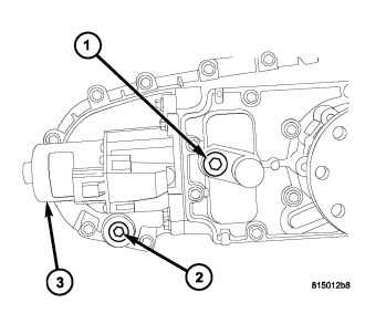
1. Place the transfer case in a shallow pan and remove the fill (1) and drain (2) plugs to drain the remainder of the fluid.
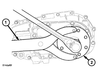
2. Using Holder C-3281 (1), remove the rear flange (2) nut.
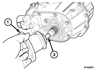
3. Remove the rear output flange (1) from the main shaft (2). If necessary, use a suitable 2 or 3 jaw puller to remove the output flange.
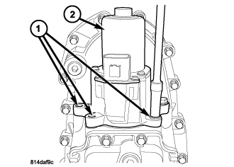
4. Remove the bolts (1) holding the shift motor and mode sensor assembly (2) to the transfer case.
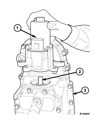
5. Remove the shift motor and mode sensor assembly (1) from the shift sector (2) and the transfer case (3).
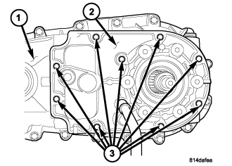
6. If necessary, remove the bolts holding the transfer case damper to the transfer case and remove the damper.
7. Remove the bolts (3) holding the rear cover (2) onto the rear housing (1).
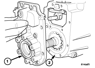
NOTE: Use the pry slots provided and take care not to damage the sealing surface.
8. Remove the rear cover (1) from the rear housing (2).
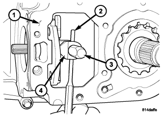
NOTE: Rotate the sector upward to ease the removal of the roll-pin.
9. Using a suitable punch, remove the roll-pin (2) holding the sector roller (4) to the shift rail (3).
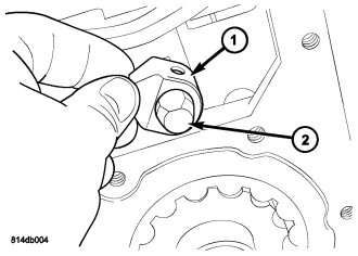
10. Remove the sector roller (1) from the shift rail (2).
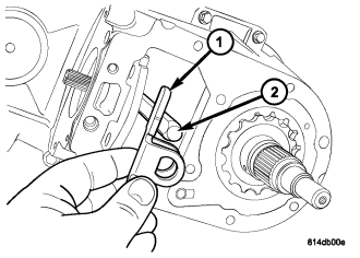
11. Remove the anti-rotation bracket (1) from the shift rail (2).
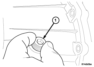
12. Remove the clutch lever rail plug (1) from the rear housing.
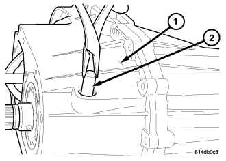
13. Remove the clutch lever rail (2) from the rear housing (1).
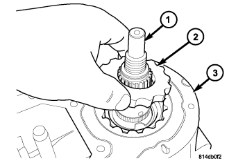
14. Remove the oil pump inner rotor (2) from the main shaft (1) and rear housing (3).
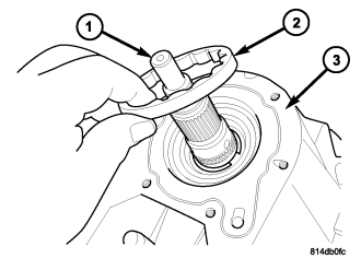
15. Remove the oil pump outer rotor (2) from the main shaft (1) and rear housing (3).
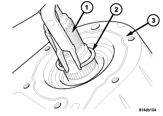
NOTE: Pull upward on the main shaft to ease the removal of the main shaft retaining ring.
16. Remove the rear output shaft (1) retaining ring (2).
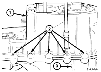
17. Remove the bolts (2) holding the rear housing (1) to the front housing (3).
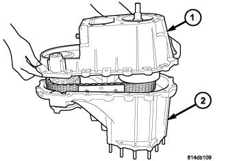
NOTE: Some prying may be necessary to break the seal between the front and rear case. Use care to not damage the sealing surfaces.
18. Remove the rear housing (1) from the front housing (2).
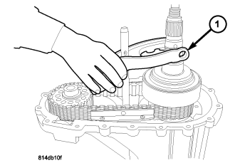
19. Remove the clutch lever assembly (1) from the mainshaft and shift rail.
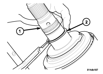
20. Remove the thrust bearing support plate retaining ring (2) from the main shaft (1).
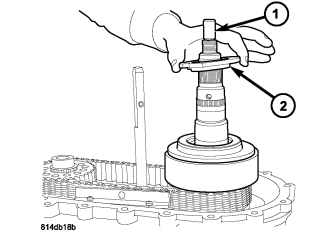
21. Remove the thrust bearing support plate (2) from the main shaft (1).
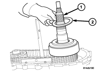
22. Remove the thrust bearing (2) from the main shaft (1).
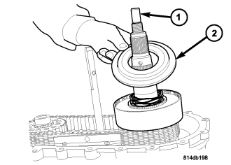
23. Remove the clutch pressure plate (2) from the main shaft (1) and clutch assembly.
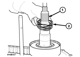
24. Remove the wave spring (2) from the main shaft (1).
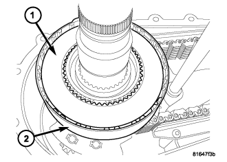
25. Remove the top (inner teeth) clutch plate (1) from the clutch retainer (2).
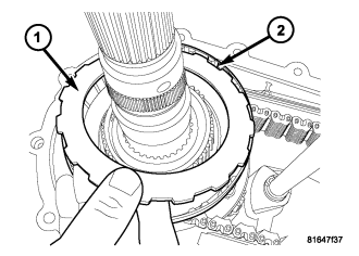
26. Continue removing clutch plates from the clutch retainer (2) until the bottom (outer lugs) clutch plate (1) is removed. Keep the discs in their original sequence if the discs are to be reused.
ASSEMBLY
NOTE: Soak new clutch friction plates in transfer case fluid for 20 minutes prior to installation.
1. Install the bottom (outer lugs) clutch plate (1) into the clutch retainer (2). Continue installing clutch plates, a disc with inner teeth followed by a disc with outer lugs, into the clutch retainer (2) .
2. install the top (inner teeth) clutch plate (1) into the clutch retainer (2).
3. Install the wave spring (2) onto the main shaft (1).
CAUTION: When installing the clutch pressure plate, make sure that the wave spring remains piloted on the underside of the plate. Check that the spring does not protrude between the plate and the mainshaft.
4. Install the clutch pressure plate (2) onto the main shaft (1) and clutch assembly.
5. Install the thrust bearing (2) onto the main shaft (1).
6. Install the thrust bearing support plate (2) onto the main shaft (1).
NOTE: The clutch pressure plate must be engaged with the inner drum and held down when installing the retaining ring.
7. Install the thrust bearing support plate retaining ring (2) onto the main shaft (1).
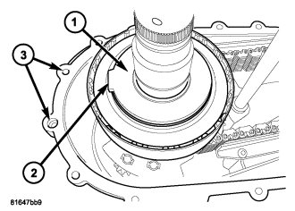
8. Rotate the thrust bearing support plate (1) so that the tab (2) is pointed between the two bolt holes (3) as shown.
9. Install the clutch lever assembly (1) onto the mainshaft and shift rail.
10. Apply bead of Mopar® Gasket Maker, or equivalent, to mating surface of front case. Keep sealer bead width to maximum of 3 mm (0.125 inch). Do not use excessive amount of sealer as excess will be displaced into case interior and potentially clog the oil pump screen.
11. Verify that the tab on the thrust bearing support plate is aligned with the housing alignment dowel furthest from the front output shaft.
12. Install the rear housing (1) into the front housing (2).
13. Install the bolts (2) to hold the rear housing (1) to the front housing (3). Tighten the bolts at the dowel locations first, then the remainder of the bolts in a criss-cross pattern. Tighten the bolts to 27 N·m (20 ft.lbs.).
NOTE: Pull up on the main shaft when installing the retaining ring to ensure that the ring is fully engaged into the groove.
14. Install the rear main shaft (1) retaining ring (2).
Lubricate the oil pump components with transmission fluid before installation.
15. Install the oil pump outer rotor (2) onto the main shaft (1) and into the rear housing (3).
16. Install the oil pump inner rotor (2) onto the main shaft (1) and into the rear housing (3).
17. Install the clutch lever rail (2) into the rear housing (1) and clutch lever.
18. Install the clutch lever rail plug (1) into the rear housing.
19. Install the anti-rotation bracket (1) onto the shift rail (2).
20. Install the sector roller (1) onto the shift rail (2).
21. Using a suitable punch, align the holes in the sector roller with the hole in the shift rail and install the roll-pin to secure the sector roller to the shift rail.
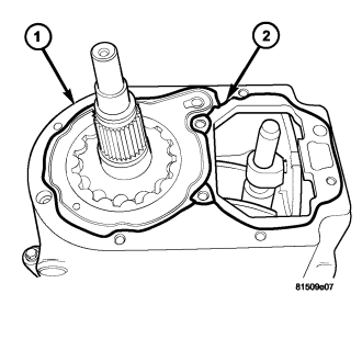
22. Apply bead of Mopar® Gasket Maker, or equivalent, to mating surface of rear housing as shown (2). Keep sealer bead width to maximum of 3 mm (1/8 inch). Do not use excessive amount of sealer as excess could be displaced into the oil pump.
23. Install the rear cover (1) onto the rear housing (2).
24. Install the bolts (3) holding the rear cover (2) onto the rear housing (1). Tighten the bolts at the dowel locations first, then the remainder of the bolts in a criss-cross pattern. Tighten the bolts to 27 N·m (20 ft.lbs.).
25. Install the shift motor and mode sensor assembly (1) onto the shift sector (2) and the transfer case (3).
26. Install the bolts (1) to hold the shift motor and mode sensor assembly (2) to the transfer case. Tighten the bolts to 27 N·m (20 ft.lbs.).
27. If necessary, install the transfer case damper onto the transfer case.
28. Install the rear output flange (1) onto the main shaft (2).
29. Using Holder C-3281 (1), install the rear output flange (2) nut. Tighten the bolts to 122-176 N·m (90-130 ft.lbs.).