SHAFT LOCK MODULE
DESCRIPTION
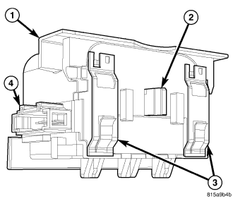
A shaft lock module (1) is part of the premium version of the Sentry Key Immobilizer System (SKIS) in the Vehicle Theft Security System (VTSS). The premium version of the SKIS is only available in vehicles built for certain markets, where the additional features offered by this system are required. The shaft lock module is located in a bracket integral to the lower end of the steering column housing casting below the instrument panel in the passenger compartment. This unit is designed to work in conjunction with the Sentry Key REmote Entry Module (SKREEM) (also known as the Wireless Control Module/WCM) to control a locking bolt (2) that engages a machined slot in the steering shaft to prevent shaft rotation whenever there is not a valid key present in the ignition lock cylinder on the instrument panel.
The die cast aluminum shaft lock module housing has a series of integral engagement tabs and slide tabs that engage matching slots and channels integral to the mounting bracket on the steering column. When the module is fully engaged in the mounting bracket, two spring clips (3) on the module engage the bracket, locking the module securely into place. Concealed within the module is the electronic circuitry of the module, and a bi-directional electric motor that actuates the locking bolt. The module is connected through an integral connector receptacle (4) to the vehicle electrical system through a take out and connector of the instrument panel wire harness.
The mounting provisions for the shaft lock module are designed to resist unauthorized tampering. The module cannot be removed from the steering column while the locking bolt is in the locked position, or while the steering column is installed in the vehicle.
The shaft lock module unit cannot be adjusted or repaired and, if ineffective or damaged, it must be replaced.
OPERATION
The electronic circuitry within the shaft lock module contains all of the logic circuits and components to monitor and control the operation of the shaft locking bolt. The module uses a serial data bus for bi-directional communication with the Sentry Key REmote Entry Module (SKREEM) (also known as the Wireless Control Module/WCM). If the module detects a problem with the positioning or operation of the locking bolt, it sends an error message to the SKREEM. The SKREEM then stores a Diagnostic Trouble Code (DTC) and sends an electronic error message to the ElectroMechanical Instrument Cluster (EMIC) (also known as the Cab Compartment Node/CCN) over the Controller Area Network (CAN) data bus, and a SERVICE COLUMN LOCK textual message will appear in the instrument cluster reconfigurable dot matrix display.
The shaft lock module continuously monitors inputs from the SKREEM and energizes the electric motor to move the locking bolt to the locked or unlocked position based upon that input. If the SKREEM indicates that the key present in the ignition lock cylinder is invalid, the locking bolt remains in the locked position. When the SKREEM indicates that a valid key is present in the ignition lock cylinder, the shaft lock module operates a motor to move the locking bolt to the unlocked position. However, to prevent inadvertent column locking due to a failure while the vehicle is being operated, the module cannot move the locking bolt from the unlocked position to the locked position as long as a key remains in the ignition lock cylinder.
The shaft lock module receives ground at all times through a hard wired remote ground point. The module receives battery voltage to operate and to move the locking bolt in the unlocked direction on a fused B(+) circuit through a fuse in the Junction Block (JB), and receives battery voltage to operate the locking bolt in the locked direction only when the key is removed from the ignition switch. These connections allow the module to remain operational, regardless of the ignition switch position.
For added system security, the shaft lock module learns a unique Secret Key code from the SKREEM over the serial data bus upon initialization. This code is stored in the memory of the module and cannot be changed. Therefore, if the SKREEM requires service replacement, a new shaft lock module will also be required. Another security code, called a PIN, is used to gain access to the SKREEM Secured Access Mode. The Secured Access Mode is required during service to initialize a new shaft lock module.
The hard wired inputs to the shaft lock module may be diagnosed using conventional diagnostic tools and procedures. Refer to the appropriate wiring information. However, conventional diagnostic methods will not prove conclusive in the diagnosis of the shaft lock module or the electronic controls or communication between other modules and devices that provide some features of the Sentry Key Immobilizer System (SKIS). The most reliable, efficient, and accurate means to diagnose the shaft lock module or the electronic controls and communication related to shaft lock module operation requires the use of a diagnostic scan tool. Refer to the appropriate diagnostic information.
REMOVAL
WARNING: To avoid serious or fatal injury, on vehicles equipped with airbags, disable the supplemental restraint system before attempting any steering wheel, steering column, airbag, seat belt tensioner, impact sensor, or instrument panel component diagnosis or service. Disconnect and isolate the battery negative (ground) cable, then wait two minutes for the system capacitor to discharge before performing further diagnosis or service. This is the only sure way to disable the supplemental restraint system. Failure to take the proper precautions could result in accidental airbag deployment.
NOTE: The shaft lock module cannot be removed from the steering column while the locking bolt is in the locked position without irreversibly damaging the column. Before attempting service, insert a valid ignition key into the ignition lock cylinder, then rotate the steering wheel from side to side. If the steering wheel can be rotated, the locking bolt is in the unlocked position. Leave the key in the ignition lock cylinder until service has been completed. If the steering wheel cannot be rotated, test and repair the wiring circuits between the module and the ignition switch as required. If no problem is found in these circuits, the module has failed with the locking bolt in the locked position and both the module and the steering column must be replaced with new units.
1. Insert a valid ignition key into the ignition lock cylinder to move the shaft lock module locking bolt to the unlocked position. Leave the key in the lock cylinder while the shaft lock module service is being completed.
2. Disconnect and isolate the battery negative cable.
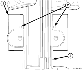
3. Remove the steering column (3) from the vehicle. (Refer to 19 - STEERING/COLUMN - REMOVAL).
4. Depress the two spring clips that secure the shaft lock module to the mounting bracket (1) on the steering column by inserting a suitable drift or punch into the release holes (2) on the upper surface of the bracket opposite the module.
5. While holding the spring clips depressed, slide the module toward the base of the column far enough to disengage the engagement tabs and slide tabs on the module from the slots and channels in the bracket.
6. Remove the module from the steering column.
INSTALLATION
WARNING: To avoid serious or fatal injury, on vehicles equipped with airbags, disable the supplemental restraint system before attempting any steering wheel, steering column, airbag, seat belt tensioner, impact sensor, or instrument panel component diagnosis or service. Disconnect and isolate the battery negative (ground) cable, then wait two minutes for the system capacitor to discharge before performing further diagnosis or service. This is the only sure way to disable the supplemental restraint system. Failure to take the proper precautions could result in accidental airbag deployment.
1. Be certain that a valid ignition key is still present in the ignition lock cylinder. Leave the key in the lock cylinder while the shaft lock module service is being completed.
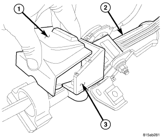
2. Align the engagement and slide tabs integral to the housing of the shaft lock module (1) with the slots and channels in the mounting bracket (3) on the steering column (2).
3. Slide the module toward the top of the column far enough for the spring clips on the module to engage the bracket.
4. Reinstall the steering column into the vehicle. (Refer to 19 - STEERING/COLUMN - INSTALLATION).
5. Reconnect the battery negative cable.
NOTE: If the shaft lock module has been replaced with a new unit, a diagnostic scan tool MUST be used to initialize the new module before the vehicle can be operated. (Refer to 8 - ELECTRICAL/VEHICLE THEFT SECURITY/SENTRY KEY REMOTE ENTRY MODULE - STANDARD PROCEDURE - SKIS INITIALIZATION).