MOTOR-REAR WINDOW WIPER
DESCRIPTION
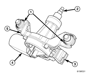
The rear wiper motor (4) is concealed within the liftgate, below the liftgate glass and behind the liftgate inner trim panel. The end of the motor output shaft (2) that extends through the liftgate outer panel to drive the rear wiper arm and blade is the only visible component of the rear wiper motor. A rubber bezel and grommet is engaged within the output shaft hole of the liftgate outer panel and seals the output shaft where it passes through the panel. An integral connector receptacle (3) connects the rear wiper motor to the vehicle electrical system through a dedicated take out and connector of the liftgate wire harness. The rear wiper motor consists of the following major components:
- Bracket (5) - The rear wiper motor bracket consists of a molded plastic mounting plate for the wiper motor that is secured with screws to the wiper motor housing, and through two screws with rubber isolators (1) to the liftgate inner panel.
- Electronic Controls - The rear wiper motor electronic controls include the rear wiper system electronic logic. The electronic controls for the motor include an electronic speed control that speeds the wiper blade near the center of the glass, but slows the wiper blade during directional reversals at each end of the wipe pattern and during wiper arm and blade off-the-glass parking for quieter operation.
- Motor - The single-speed permanent magnet rear wiper motor is secured to the rear wiper motor bracket. The wiper motor includes an integral transmission, motor output shaft, an automatic resetting circuit breaker and the rear wiper motor park switch.
The rear wiper motor cannot be adjusted or repaired. If any component of the motor is ineffective or damaged, the entire rear wiper motor unit must be replaced. The motor output shaft bezel and grommet, and the mounting nut are available for individual service replacement.
OPERATION
The rear wiper motor operation is controlled by the rear wiper relay, which controls battery current flow to the rear wiper motor based upon control outputs from the Front Control Module (FCM). The FCM uses internal programming and electronic messages received over the Controller Area Network (CAN) data bus from the Steering Control Module (SCM) to determine when to energize or de-energize the rear wiper relay.
The rear wiper motor park switch is a single pole, single throw, momentary switch within the wiper motor that is mechanically actuated by the wiper motor transmission components. The park switch alternately closes and opens a path to ground for the rear wiper motor control circuit input to the wiper motor electronic controls, depending upon the position of the rear wiper blade on the liftgate glass.
The motor control electronics also monitor a hard wired input from the liftgate flip-up glass ajar switch to determine whether the glass is opened or closed, and two hard wired signal inputs from the SCM indicating the mode selected with the rear wiper switch circuitry of the right (wiper) multi-function switch. These inputs allow the electronic logic circuits to control all of the electronic features of rear wiper motor operation and to keep the motor energized long enough to complete its current wipe cycle and park the wiper blade after the wiper system or the ignition switch has been turned OFF, or when the liftgate flip-up glass has been opened.
The rear wiper motor is grounded at all times through a take out with an eyelet terminal connector in the body wire harness that is secured to a ground location in the passenger compartment. The automatic resetting circuit breaker protects the motor from overloads. The rear wiper motor transmission converts the rotary output of the wiper motor to the back and forth wiping motion of the rear wiper arm and blade on the liftgate flip-up glass.
The hard wired inputs and outputs of the rear wiper motor may be diagnosed using conventional diagnostic tools and procedures. Refer to the appropriate wiring information. However, conventional diagnostic methods will not prove conclusive in the diagnosis of the rear wiper motor or the electronic controls or communication between other modules and devices that provide some features of the rear wiper and washer system. The most reliable, efficient, and accurate means to diagnose the rear wiper motor or the electronic controls and communication related to rear wiper motor operation requires the use of a diagnostic scan tool. Refer to the appropriate diagnostic information.
REMOVAL
1. Disconnect and isolate the battery negative cable.
2. Remove the rear wiper arm from the rear wiper motor output shaft. (Refer to 8 - ELECTRICAL/WIPERS/WASHERS/WIPER ARM - REMOVAL - REAR).
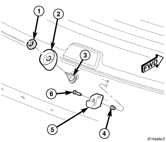
3. Remove the nut (1) that secures the output shaft (3) and the bezel (2) to the liftgate outer panel.
4. Remove the bezel from the rear wiper motor output shaft.
5. Remove the trim panel from the liftgate inner panel. (Refer to 23 - BODY/DECKLID/HATCH/LIFTGATE/TAILGATE/TRIM PANEL - REMOVAL).
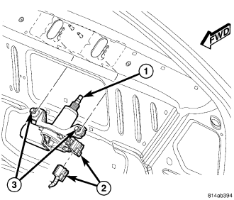
6. Disconnect the liftgate wire harness connector from the rear wiper motor (2).
7. Loosen the two screws (3) that secure the motor mounting bracket to the bracket within the liftgate.
8. Slide the wiper motor forward far enough to disengage the two mounting screws from the keyed holes in the bracket within the liftgate.
9. Remove the motor from the liftgate.
INSTALLATION
1. Position the rear wiper motor and mounting bracket into the liftgate as a unit with the two mounting screws (3) loosened.
2. Insert the motor output shaft (1) through the hole in the liftgate outer panel and engage the two mounting screws into the keyed holes in the bracket within the liftgate.
3. From the outside of the liftgate, install the bezel (2) over the motor output shaft (3) and engage it in the mounting hole of the liftgate outer panel.
4. Install and tighten the nut (1) that secures the bezel and the output shaft to the liftgate outer panel. Tighten the nut to 5 N·m (43 in. lbs.).
5. From the inside of the liftgate, tighten the two screws that secure the motor mounting bracket to the bracket within the liftgate. Tighten the screws to 6 N·m (50 in. lbs.).
6. Reconnect the liftgate wire harness connector to the wiper motor connector receptacle (2).
7. Reinstall the trim panel onto the liftgate inner panel. (Refer to 23 - BODY/DECKLID/HATCH/LIFTGATE/TAILGATE/TRIM PANEL - INSTALLATION).
8. Reinstall the rear wiper arm onto the output shaft. (Refer to 8 - ELECTRICAL/WIPERS/WASHERS/WIPER ARMS - INSTALLATION - REAR).
9. Reconnect the battery negative cable.