RESERVOIR - VACUUM
DESCRIPTION
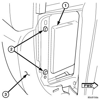
The reservoir (1) is located behind, and at the outer end of the instrument panel . To gain access for testing or removal, remove glovebox assembly. Also remove fuse box access cover panel at end of instrument panel. On vehicles equipped with LHD (Left Hand Drive), this fuse access panel is located at right end of instrument panel. On vehicles equipped with RHD (Right Hand Drive), this access panel is located at left end of instrument panel.
OPERATION
The vacuum reservoir is used to supply the vacuum needed to maintain proper speed control operation when engine vacuum drops, such as in climbing a grade while driving. A one-way check valve is used in the vacuum line between the reservoir and the vacuum source. This check valve is used to trap engine vacuum in the reservoir. On certain vehicle applications, this reservoir is shared with the heating/air-conditioning system. The vacuum reservoir cannot be repaired and must be replaced if faulty.
DIAGNOSIS AND TESTING - VACUUM RESERVOIR
1. Disconnect vacuum hose at speed control servo and install a vacuum gauge into the disconnected hose.
2. Start engine and observe gauge at idle. Vacuum gauge should read at least ten inches of mercury.
3. If vacuum is less than ten inches of mercury, determine source of leak. Check vacuum line to engine for leaks. Also check actual engine intake manifold vacuum. If manifold vacuum does not meet this requirement, check for poor engine performance and repair as necessary.
4. If vacuum line to engine is not leaking, check for leak at vacuum reservoir. To locate and gain access to reservoir, refer to Vacuum Reservoir Removal/Installation in this group. Disconnect vacuum line at reservoir and connect a hand-operated vacuum pump to reservoir fitting. Apply vacuum. Reservoir vacuum should not bleed off. If vacuum is being lost, replace reservoir.
5. Verify operation of one-way check valve and check it for leaks. Certain models may be equipped with 2 check-valves.
a. Locate one-way check valve. The valve is located in vacuum line between vacuum reservoir and engine vacuum source. Disconnect vacuum hoses (lines) at each end of valve.
b. Connect a hand-operated vacuum pump to reservoir end of check valve. Apply vacuum. Vacuum should not bleed off. If vacuum is being lost, replace one-way check valve.
c. Connect a hand-operated vacuum pump to vacuum source end of check valve. Apply vacuum. Vacuum should flow through valve. If vacuum is not flowing, replace one-way check valve. Seal the fitting at opposite end of valve with a finger and apply vacuum. If vacuum will not hold, diaphragm within check valve has ruptured. Replace valve.
REMOVAL
The vacuum reservoir (1) is located behind, and at the outer end of the instrument panel . To gain access for testing or removal, remove glovebox assembly. Also remove fuse box access cover panel at end of instrument panel. On vehicles equipped with LHD (Left Hand Drive), this fuse access panel is located at right end of instrument panel. On vehicles equipped with RHD (Right Hand Drive), this access panel is located at left end of instrument panel.
1. Remove glovebox assembly. Access to reservoir vacuum line and fitting can now be made.
2. Remove vacuum line at reservoir.
3. Remove fuse access cover panel at end of instrument panel.
4. Through fuse access opening, remove two horizontally mounted screws (2) .
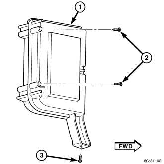
5. From bottom of instrument panel, remove one vertically mounted screw (3) .
6. Remove reservoir from instrument panel.
INSTALLATION
1. Position reservoir (1) to instrument panel.
2. Install two horizontal mounting screws (2) but do not tighten.
3. Install one vertically mounted screw (3). Tighten all three mounting screws to 3 N·m (20 in. lbs.).
4. Connect vacuum line to reservoir fitting.
5. Install glovebox assembly.
6. Install fuse box access cover panel.