SERVO-SPEED CONTROL
DESCRIPTION
The servo unit consists of a solenoid valve body, and a vacuum chamber. The solenoid valve body contains three solenoids:- Vacuum
- Vent
- Dump
The vacuum chamber contains a diaphragm with a cable attached to control the throttle linkage.
OPERATION
The Powertrain Control Module (PCM) controls the solenoid valve body. The solenoid valve body controls the application and release of vacuum to the diaphragm of the vacuum servo. The servo unit cannot be repaired and is serviced only as a complete assembly.
Power is supplied to the servo's by the PCM through the brake switch. The PCM controls the ground path for the vacuum and vent solenoids.
The dump solenoid is energized anytime it receives power. If power to the dump solenoid is interrupted, the solenoid dumps vacuum in the servo. This provides a safety backup to the vent and vacuum solenoids.
The vacuum and vent solenoids must be grounded at the PCM to operate. When the PCM grounds the vacuum servo solenoid, the solenoid allows vacuum to enter the servo and pull open the throttle plate using the cable. When the PCM breaks the ground, the solenoid closes and no more vacuum is allowed to enter the servo. The PCM also operates the vent solenoid via ground. The vent solenoid opens and closes a passage to bleed or hold vacuum in the servo as required.
The PCM duty cycles the vacuum and vent solenoids to maintain the set speed, or to accelerate and decelerate the vehicle. To increase throttle opening, the PCM grounds the vacuum and vent solenoids. To decrease throttle opening, the PCM removes the grounds from the vacuum and vent solenoids. When the brake is released, if vehicle speed exceeds 30 mph to resume, 35 mph to set, and the RES/ACCEL switch has been depressed, ground for the vent and vacuum circuits is restored.
REMOVAL
1. Disconnect negative battery cable at battery.
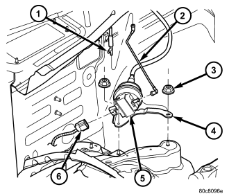
2. Disconnect vacuum line (2) at servo .
3. Disconnect electrical connector (6) at servo .
4. Remove coolant bottle nuts/bolts. Position bottle forward a few inches.
5. Disconnect servo cable at throttle body. Refer to servo Cable Removal/Installation.
6. Remove servo bracket mounting nuts (3) .
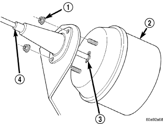
7. Remove two mounting nuts (1) holding servo cable sleeve to bracket .
8. Pull speed control cable sleeve and servo away from servo mounting bracket to expose cable retaining clip (3) and remove clip. Note: The servo mounting bracket displayed in graphic is a typical bracket and may/may not be applicable to this model vehicle.
9. Remove servo from mounting bracket. While removing, note orientation of servo to bracket.
INSTALLATION
1. Position servo to mounting bracket.
2. Align hole in cable connector with hole in servo pin. Install cable-to-servo retaining clip (3).
3. Insert servo mounting studs through holes in servo mounting bracket.
4. Install servo-to-mounting bracket nuts (1) and tighten. Refer to torque specifications.
5. Install servo mounting bracket-to-body nuts (3) and tighten. Refer to torque specifications.
6. Connect vacuum line (2) at servo.
7. Connect electrical connector (6) at servo.
8. Connect servo cable to throttle body. Refer to servo Cable Removal/Installation.
9. Install coolant bottle.
10. Connect negative battery cable to battery.
11. Before starting engine, operate accelerator pedal to check for any binding.