AMPLIFIER CHOKE AND RELAY
DESCRIPTION
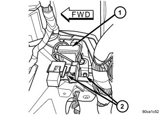
Vehicles equipped with the premium speaker package have a amplifier choke and relay (1). The amplifier choke and relay is mounted to the lower instrument panel above the pedals and towards the instrument panel center stack.
The amplifier choke and relay should be checked if there is no sound output from the speakers. The amplifier choke and relay can not be repaired or adjusted and, if faulty or damaged, the unit must be replaced.
OPERATION
The amplifier choke and relay is used to control the supply of fused battery current to the front door speaker-mounted dual amplifiers. The speaker relay is energized by a fused 12 volt output from the radio receiver whenever the radio is turned on. For complete circuit diagrams, refer to the appropriate wiring information. The wiring information includes wiring diagrams, proper wire and connector repair procedures, details of wire harness routing and retention, connector pin-out information and location views for the various wire harness connectors, splices and grounds.
DIAGNOSIS AND TESTING - AMPLIFIER CHOKE AND RELAY
Any diagnosis of the Audio system should begin with the use of scan tool. For information on the use of the scan tool, refer to the appropriate Diagnostic information.
The amplifier choke and relay is used to switch power to the individual speaker amplifiers used with the premium speaker package. The amplifier choke and relay is serviced only as a unit. If all of the speakers are inoperative the amplifier choke and relay should be inspected. Before replacement, make the following inspections of the amplifier choke and relay circuits. For complete circuit diagrams, refer to the appropriate wiring information. The wiring information includes wiring diagrams, proper wire and connector repair procedures, details of wire harness routing and retention, connector pin-out information and location views for the various wire harness connectors, splices and grounds.
1. Check the fused B(+) fuse in the junction block. If OK, go to STEP 2. If not OK, replace the faulty fuse.
2. Check for battery voltage at the fused B(+) fuse in the junction block. If OK, go to STEP 3. If not OK, repair the open fused B(+) circuit to the battery as required.
3. Disconnect the instrument panel wire harness connector from the amplifier choke and relay. Check for battery voltage at the fused B(+) circuit cavity of the instrument panel wire harness connector for the amplifier choke and relay. If OK, go to STEP 4. If not OK, repair the open fused B(+) circuit to the junction block fuse as required.
4. Probe the ground circuit cavity of the instrument panel wire harness connector for the amplifier choke and relay. Check for continuity to a good ground. There should be continuity. If OK, go to STEP 5. If not OK, repair the open ground circuit to ground as required.
5. Turn the ignition switch to the RUN position and turn the radio ON. Check for battery voltage at the radio 12-volt output circuit cavity of the instrument panel wire harness connector for the amplifier choke and relay. If OK, go to STEP 6. If not OK, repair the open radio 12-volt output circuit to the radio as required.
6. Turn the radio and ignition switches to the OFF position. Reconnect the instrument panel wire harness connector to the amplifier choke and relay. Check for battery voltage at the amplified speaker (+) circuit cavity of the instrument panel wire harness connector for the amplifier choke and relay. There should be zero volts. Turn the ignition and radio switches to the ON position. There should now be battery voltage. If OK, repair the open amplified speaker (+) circuits to the speaker-mounted amplifiers as required. If not OK, replace the faulty amplifier choke and relay.
REMOVAL
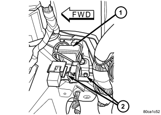
1. Disconnect and isolate the battery negative cable.
2. Remove knee blocker cover and knee blocker.
3. Disconnect the electrical harness connector from the amplifier choke and relay (1).
4. Remove mounting fasteners and amplifier choke and relay.
INSTALLATION
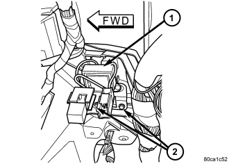
1. Install the amplifier choke and relay (1).
2. Install and tighten the mounting fasteners.
3. Connect the electrical harness connector.
4. Install knee blocker cover and knee blocker.
5. Connect the battery negative cable.