SPEAKER
DESCRIPTION
STANDARD
The standard equipment speaker system includes speakers in six locations. One 6.4 centimeter (2.50 inch) diameter speaker is installed on each end of the instrument panel top pad. One 16.5 centimeter (6.5 inch) full-range speaker is located in each front door. There is also one full-range 16.5 centimeter (6.5 inch) diameter full-range speaker located in each rear door.
PREMIUM
The optional premium speaker system features six Premium model speakers in six locations. Each of the standard speakers is replaced with Premium model speakers. One 6.4 centimeter (2.50 inch) diameter speaker is installed on each end of the instrument panel top pad. One 16.5 centimeter (6.5 inch) Premium woofer is located in each front door. There is also one full-range 16.5 centimeter (6.5 inch) diameter Premium full-range speaker located in each rear door. The premium speaker system also includes a power amplifier mounted to each front door speaker. The total available power of the premium speaker system is about 160 watts.
OPERATION
Two wires connected to each speaker, one feed circuit (+) and one return circuit (–), allow the audio output signal electrical current to flow through the voice coil. For complete circuit diagrams, refer to the appropriate wiring information. The wiring information includes wiring diagrams, proper wire and connector repair procedures, details of wire harness routing and retention, connector pin-out information and location views for the various wire harness connectors, splices and grounds.
DIAGNOSIS AND TESTING - SPEAKER
Any diagnosis of the Audio system should begin with the use of scan tool. For information on the use of the scan tool, refer to the appropriate Diagnostic information.
Refer to the appropriate wiring information.
WARNING: Disable the airbag system before attempting any steering wheel, steering column, seat belt tensioner, side airbag, or instrument panel component diagnosis or service. Disconnect and isolate the battery negative (ground) cable, then wait two minutes for the airbag system capacitor to discharge before performing further diagnosis or service. This is the only sure way to disable the airbag system. Failure to take the proper precautions could result in accidental airbag deployment and possible personal injury.
CAUTION: The speaker output of the radio is a “floating ground” system. Do not allow any speaker lead to short to ground, as damage to the radio may result.
NOTE: If poor sound quality is noted in the audio system, check the Cabin Equalization curve programmed in the BCM. Make sure a base speaker system has the Base Cabin Equalization Curve programmed to the vehicle. If the vehicle has a premium speaker system, make sure the Premium Cabin Equalization Curve is programmed to the vehicle
1. If all speakers are inoperative, check the fuses in the Junction Block (JB). If OK, go to Step 2. If not OK, repair the shorted circuit or component as required and replace the faulty fuse.
2. Turn the ignition switch to the ON position. Turn the radio receiver ON. Adjust the balance and fader control controls to check the performance of each individual speaker. Note the speaker locations that are not performing correctly. Go to Step 3.
3. Turn the radio receiver OFF. Turn the ignition OFF. Disconnect and isolate the battery negative cable. If vehicle is not equipped with an amplifier, remove the radio receiver. If vehicle is equipped with an amplifier. disconnect wire harness connector at output side of amplifier. Go to Step 4.
4. Check both the speaker feed (+) circuit and return (-) circuit cavities for the inoperative speaker at the radio receiver wire harness connector for continuity to ground. There should be no continuity. If OK, go to Step 5. If not OK, repair the shorted speaker feed (+) and/or return (-) circuits(s) to the speaker as required.
5. Disconnect wire harness connector at the inoperative speaker. Check for continuity between the speaker feed (+) circuit cavities of the radio receiver wire harness connector and the speaker wire harness connector. Repeat the check between the speaker return (-) circuit cavities of the radio receiver wire harness connector and the speaker wire harness connector. In each case, there should be continuity. If OK, replace the faulty speaker. If not OK, repair the open speaker feed (+) and/or return (-) circuits(s) as required.
REMOVAL
FRONT DOOR
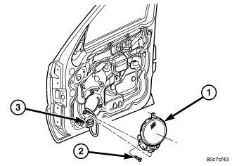
1. Disconnect and isolate the battery negative cable.
2. Remove the front door trim panel (Refer to 23 - BODY/DOOR - FRONT/TRIM PANEL - REMOVAL).
3. Remove the speaker mounting fasteners.
4. Remove the speaker (1) from the door and disconnect the wire harness connector.
INSTRUMENT PANEL
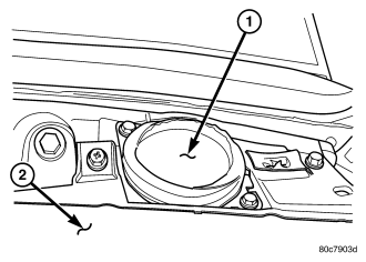
1. Disconnect and isolate the battery negative cable.
2. Remove the A-pillar trim (Refer to 23 - BODY/INTERIOR/A-PILLAR TRIM - REMOVAL).
3. Remove instrument panel top cover (Refer to 23 - BODY/INSTRUMENT PANEL/INSTRUMENT PANEL TOP COVER - REMOVAL).
4. Remove speaker mounting fasteners.
5. Remove speaker (1) and disconnect the wire harness connector.
REAR DOOR
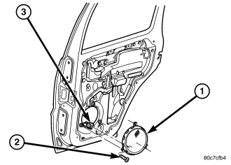
1. Disconnect and isolate the battery negative cable.
2. Remove the rear door trim panel (Refer to 23 - BODY/DOORS - REAR/TRIM PANEL - REMOVAL).
3. Remove the speaker mounting fasteners.
4. Remove the speaker (1) from the door and disconnect the wire harness connector (3).
INSTALLATION
FRONT DOOR
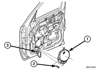
1. Connect the wire harness connector and install the speaker to the door.
2. Install the speaker mounting screws. Tighten to 2 N·m (20 in. lbs.).
3. Install the front door trim panel (Refer to 23 - BODY/DOOR - FRONT/TRIM PANEL - INSTALLATION).
4. Connect the battery negative cable.
INSTRUMENT PANEL
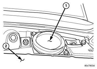
1. Connect wire harness connector and install speaker.
2. Install speaker mounting screws. Tighten to 2 N·m (20 in. lbs.).
3. Install instrument panel top cover (Refer to 23 - BODY/INSTRUMENT PANEL/INSTRUMENT PANEL TOP COVER - INSTALLATION).
4. Install the A-pillar trim (Refer to 23 - BODY/INTERIOR/A-PILLAR TRIM - INSTALLATION).
5. Connect the battery negative cable.
REAR DOOR
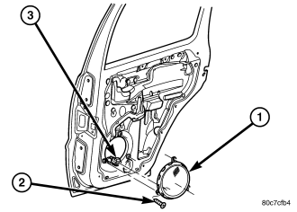
1. Connect the wire harness connector and install the speaker to the door.
2. Install the speaker mounting screws. Tighten to 2 N·m (20 in. lbs.).
3. Install the rear door trim panel (Refer to 23 - BODY/DOORS - REAR/TRIM PANEL - INSTALLATION).
4. Connect the battery negative cable.