P0871-OD PRESSURE SWITCH RATIONALITY
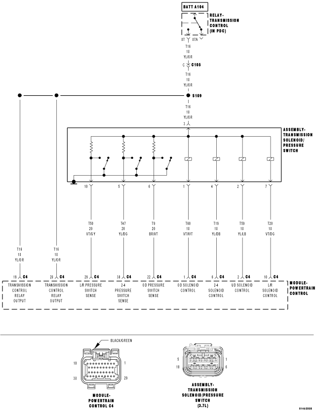
For a complete wiring diagram Refer to Section 8W.
Theory of Operation
The Transmission system uses three pressure switches to monitor the fluid pressure in the LR, 2/4, and OD elements. The pressure switches are continuously monitored for the correct states in each gear. Normal operation will be experienced if no other codes are present. Transmission Control System will ignore the code. Limp-in condition will only occur if DTC P0871 is present with a DTC P0706.
- When Monitored:
Whenever the engine is running.
- Set Condition:
The DTC is set if one of the pressure switches are open or closed at the wrong time in a given gear. If the problem is identified for 3 successive key starts, the transmission will go into Limp-in mode and the MIL will turn on after 10 seconds of vehicle operation.
| Possible Causes |
| RELATED TRANSMISSION RELAY DTCS PRESENT |
| LOSS OF PRIME DTC PRESENT |
| (T9) OD PRESSURE SWITCH SENSE CIRCUIT OPEN |
| (T9) OD PRESSURE SWITCH SENSE CIRCUIT SHORT TO GROUND |
| (T9) OD PRESSURE SWITCH SENSE CIRCUIT SHORT TO VOLTAGE |
| TRANSMISSION SOLENOID/PRESSURE SWITCH ASSEMBLY |
| POWERTRAIN CONTROL MODULE |
Always perform the Pre-Diagnostic Troubleshooting procedure before proceeding. (Refer to 21 - TRANSMISSION/TRANSAXLE/AUTOMATIC - 42RLE - DIAGNOSIS AND TESTING).
| GEAR | L/R | 2/4 | OD |
| R | OPEN | OPEN | OPEN |
| P/N | CLOSED | OPEN | OPEN |
| 1st | CLOSED | OPEN | OPEN |
| 2nd | OPEN | CLOSED | OPEN |
| D | OPEN | OPEN | CLOSED |
| OD | OPEN | CLOSED | CLOSED |
Diagnostic Test
1. DETERMINING IF RELATED TRANSMISSION RELAY DTCS ARE PRESENTWith the scan tool, read Transmission DTCs
Are there any Transmission Control Relay DTCs present also?
Yes
- Refer to the Transmission category and perform the appropriate diagnostic procedure.
- Perform 42RLE TRANSMISSION VERIFICATION TEST.
No
- Go To 2
2. CHECK FOR LOSS OF PRIME DTC
With the scan tool, check for other Transmission DTCs.
Is the DTC P0944 present also?
Yes
- Refer to the Transmission category and perform the appropriate diagnostic procedure.
- Perform 42RLE TRANSMISSION VERIFICATION TEST.
No
- Go To 3
3. CHECK TO SEE IF P0841 IS CURRENT
With the scan tool, view DTCs.
Is the status Active for this DTC or is the STARTS SINCE SET counter 2 or less?
Yes
- Go To 4
No
- Go To 10
4. PCM AND WIRING
Turn the ignition off to the lock position.
Remove the Starter Relay.
CAUTION: Removal of the Starter Relay is to prevent a Transmission NO RESPONSE condition and to disable the starter.
Install the Transmission Simulator, Miller tool #8333 and the Electronic Transmission Adapter kit.
NOTE: Check connectors - Clean/repair as necessary.
Ignition on, engine not running.
With the Transmission Simulator, turn the Pressure Switch selector to OD.
With the scan tool, monitor the OD Pressure Switch state while pressing the Pressure Switch Test button on the Transmission Simulator.
Did the OD Pressure Switch state change?
Yes
- Go To 8
No
- Go To 5
5. (T9) OD PRESSURE SWITCH SENSE CIRCUIT OPEN
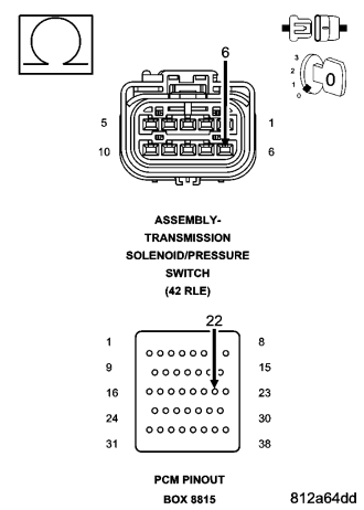
Turn the ignition off to the lock position.
Disconnect the PCM C4 harness connector.
Disconnect the Transmission Solenoid/Pressure Switch Assembly harness connector.
NOTE: Check connectors - Clean/repair as necessary.
CAUTION: Do not probe the PCM harness connectors. Probing the PCM harness connectors will damage the PCM terminals resulting in poor terminal to pin connection. Install Miller Special Tool #8815 to perform diagnosis.
Measure the resistance of the (T9) OD Pressure Switch Sense circuit from the appropriate terminal of special tool #8815 to the Transmission Solenoid/Pressure Switch Assembly harness connector.
Is the resistance above 5.0 ohms?
Yes
- Repair the (T9) OD Pressure Switch Sense circuit for an open.
- Perform 42RLE TRANSMISSION VERIFICATION TEST.
No
- Go To 6
6. (T9) OD PRESSURE SWITCH SENSE CIRCUIT SHORT TO GROUND
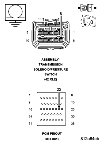
Measure the resistance between ground and the (T9) OD Pressure Switch Sense circuit.
Is the resistance below 5.0 ohms?
Yes
- Repair the (T9) OD Pressure Switch Sense circuit for a short to ground.
- Perform 42RLE TRANSMISSION VERIFICATION TEST.
No
- Go To 7
7. (T9) OD PRESSURE SWITCH SENSE CIRCUIT SHORT TO VOLTAGE
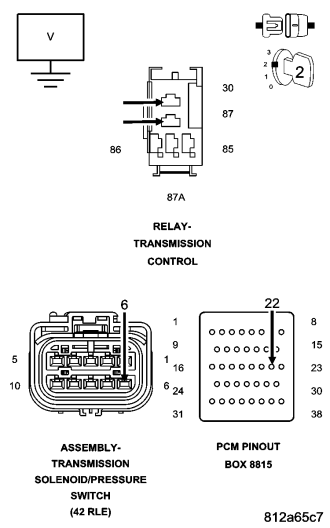
Remove the Transmission Control Relay.
NOTE: Check connectors - Clean/repair as necessary.
Connect a jumper wire between the (A104) Fused B+ circuit and (T16) Transmission Control Relay Output circuit.
Ignition on, engine not running.
Measure the voltage of the (T9) OD Pressure Switch Sense circuit.
Is the voltage above 0.5 volts?
Yes
- Repair the (T9) OD Pressure Switch Sense circuit for a short to voltage.
- Perform 42RLE TRANSMISSION VERIFICATION TEST.
No
- Go To 9
8. OD PRESSURE SWITCH
If there are no possible causes remaining, view repair.
Repair
- Replace the Transmission Solenoid/Pressure Switch Assembly per the Service Information.
- Perform 42RLE TRANSMISSION VERIFICATION TEST.
9. POWERTRAIN CONTROL MODULE
Using the schematics as a guide, inspect the wiring and connectors. Repair as necessary. Pay particular attention to all power and ground circuits.
If there are no possible causes remaining, view repair.
Repair
- Replace and program the Powertrain Control Module per the Service Information. With the scan tool perform QUICK LEARN.
- Perform 42RLE TRANSMISSION VERIFICATION TEST.
10. INTERMITTENT WIRING AND CONNECTORS
The conditions necessary to set the DTC are not present at this time.
Using the schematics as a guide, inspect the wiring and connectors specific to this circuit.
Wiggle the wires while checking for shorted and open circuits.
With the scan tool, check the DTC EVENT DATA to help identify the conditions in which the DTC was set.
Were there any problems found?
Yes
- Repair as necessary.
- Perform 42RLE TRANSMISSION VERIFICATION TEST.
No
- Test Complete.