P0122-TPS/APP CIRCUIT LOW
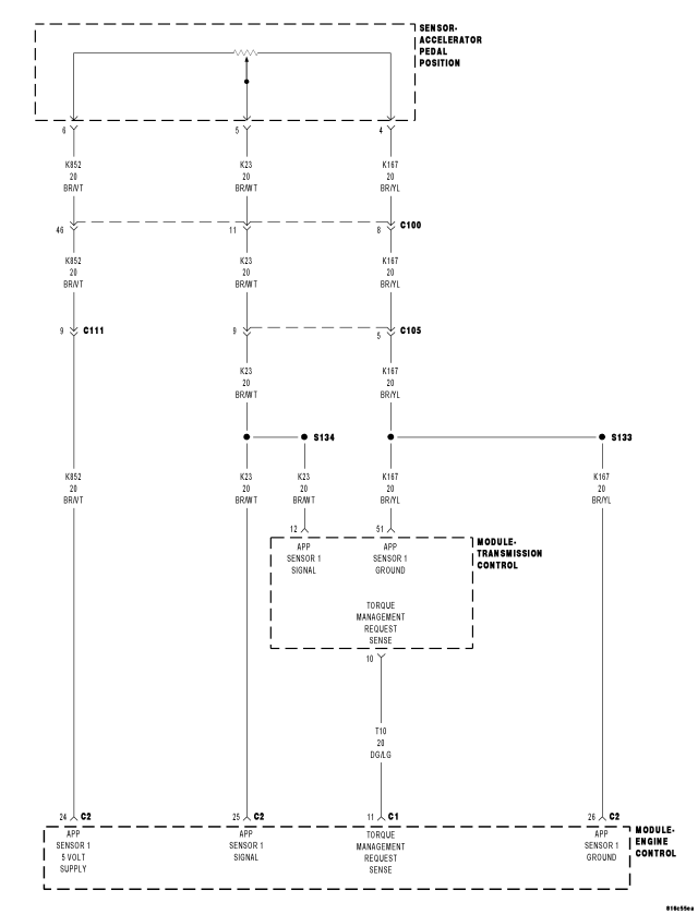
For a complete wiring diagram Refer to Section 8W.
Theory of Operation
The Accelerator Pedal Position Sensor (APPS) is a linear potentiometer. It provides the ECM and the TCM with a voltage signal proportional to the angle, or position of the accelerator pedal. The APPS signal along with inputs from other sensors is used by the ECM and the TCM to calculate the throttle position.
- When Monitored:
Continuously with the ignition on and engine running.
- Set Condition:
This DTC will set if the monitored APPS voltage drops below 0.078 volts for the period of 0.48 seconds.
| Possible Causes |
| (K23) APP SENSOR 1 SIGNAL CIRCUIT OPEN |
| (K23) APP SENSOR 1 SIGNAL CIRCUIT SHORT TO GROUND |
| ACCELERATOR PEDAL POSITION SENSOR |
| TRANSMISSION CONTROL MODULE |
Always perform the Pre-Diagnostic Troubleshooting procedure before proceeding. (Refer to 21 - TRANSMISSION/TRANSAXLE/AUTOMATIC - 45RFE/545RFE - STANDARD PROCEDURE)
Diagnostic Test
1. CHECK IF RELATED ENGINE TPS/APPS DTC'S ARE PRESENTWith the scan tool, check Engine DTC's.
Are there any Engine TPS/APPS DTCs present?
Yes
- Refer to the Drivability Category and perform the appropriate Symptom.
- Perform 45RFE/545RFE TRANSMISSION VERIFICATION TEST - VER 1. (Refer to 21 - TRANSMISSION/TRANSAXLE/AUTOMATIC - 45RFE/545RFE - STANDARD PROCEDURE)
No
- Go To 2
2. CHECK TO SEE IF THE DTC IS CURRENT
With the scan tool in Transmission Sensors, read the TPS/APPS voltage.
Is the TPS/APPS voltage below 0.1 volts?
Yes
- Go To3
No
- Go To6
3. ACCELERATOR PEDAL POSITION SENSOR
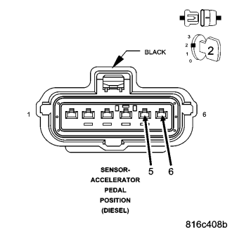
Turn the ignition off to the lock position.
Disconnect the APP Sensor harness connector.
Connect a jumper wire between the (K852) 5-volt Supply circuit and the (K23) APP Sensor 1 Signal circuit.
Ignition on, engine not running.
With the scan tool in Transmission Sensors, read the TPS/APPS voltage.
Is the TPS/APPS voltage above 4.5 volts?
Yes
- Replace the Accelerator Pedal Position Sensor per the Service Information.
- Perform 45RFE/545RFE TRANSMISSION VERIFICATION TEST - VER 1. (Refer to 21 - TRANSMISSION/TRANSAXLE/AUTOMATIC - 45RFE/545RFE - STANDARD PROCEDURE)
No
- Go To4
4. (K23) APP SENSOR 1 SIGNAL CIRCUIT OPEN
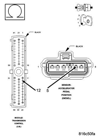
Turn the ignition off to the lock position.
Disconnect the TCM harness connector.
Measure the resistance of the (K23) APP Sensor 1 Signal circuit between the TCM harness connector and the APP Sensor harness connector.
Is the resistance above 5.0 ohms?
Yes
- Repair the (K23) APP Sensor 1 Signal circuit for an open.
- Perform 45RFE/545RFE TRANSMISSION VERIFICATION TEST - VER 1. (Refer to 21 - TRANSMISSION/TRANSAXLE/AUTOMATIC - 45RFE/545RFE - STANDARD PROCEDURE)
No
- Go To5
5. (K23) APP SENSOR 1 GROUND CIRCUIT SHORT TO GROUND
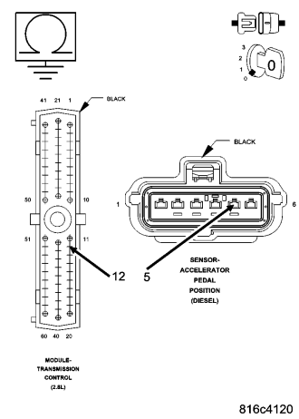
Measure the resistance between ground and the (K23) APP Sensor 1 Signal circuit.
Is the resistance below 5.0 ohms?
Yes
- Repair the (K23) APP Sensor 1 Signal circuit for a short to ground.
- Perform 45RFE/545RFE TRANSMISSION VERIFICATION TEST - VER 1. (Refer to 21 - TRANSMISSION/TRANSAXLE/AUTOMATIC - 45RFE/545RFE - STANDARD PROCEDURE)
No
- Using the schematics as a guide, check the Engine Control Module (ECM) terminals for corrosion, damage, or terminal push out. Pay particular attention to all power and ground circuits. If no problems are found, replace the ECM per the Service Information. With the scan tool, perform QUICK LEARN.
- Perform 45RFE/545RFE TRANSMISSION VERIFICATION TEST - VER 1. (Refer to 21 - TRANSMISSION/TRANSAXLE/AUTOMATIC - 45RFE/545RFE - STANDARD PROCEDURE)
6. INTERMITTENT WIRING AND CONNECTORS
The conditions necessary to set the DTC are not present at this time.
Using the schematics as a guide, inspect the wiring and connectors specific to this circuit.
Wiggle the wiring and connectors while checking for shorted and open circuits.
With the scan tool, check the DTC EVENT DATA to help identify the conditions in which the DTC was set.
Were there any problems found?
Yes
- Repair as necessary.
- Perform 45RFE/545RFE TRANSMISSION VERIFICATION TEST - VER 1. (Refer to 21 - TRANSMISSION/TRANSAXLE/AUTOMATIC - 45RFE/545RFE - STANDARD PROCEDURE)
No
- Test Complete.