CHARGING SYSTEM
DESCRIPTION
The charging system consists of:
- Generator
- Electronic Voltage Regulator (EVR) circuitry within the Powertrain Control Module (PCM)
- Ignition switch
- Battery (refer to 8, Battery for information)
- Battery temperature sensor
- Generator Lamp (if equipped)
- Check Gauges Lamp (if equipped)
- Wiring harness and connections (refer to 8, Wiring for information)
OPERATION
The charging system is turned on and off with the ignition switch. The system is on when the engine is running and the ASD relay is energized. When the ASD relay is on, voltage is supplied to the ASD relay sense circuit at the PCM. This voltage is connected through the PCM and supplied to one of the generator field terminals (Gen. Source +) at the back of the generator.
The amount of DC current produced by the generator is controlled by the EVR (field control) circuitry contained within the PCM. This circuitry is connected in series with the second rotor field terminal and ground.
Data from monitored line voltage is used by the PCM to vary the battery charging rate. This is done by cycling the ground path to control the strength of the rotor magnetic field. The PCM then compensates and regulates generator current output accordingly.
All vehicles are equipped with On-Board Diagnostics (OBD). All OBD-sensed systems, including EVR (field control) circuitry, are monitored by the PCM. Each monitored circuit is assigned a Diagnostic Trouble Code (DTC). The PCM will store a DTC in electronic memory for certain failures it detects.
The Check Gauges Lamp (if equipped) monitors: charging system voltage, engine coolant temperature and engine oil pressure. If an extreme condition is indicated, the lamp will be illuminated. This is done as reminder to check the three gauges. The signal to activate the lamp is sent via the CCD bus circuits. The lamp is located on the instrument panel. Refer to 8, Instrument Cluster for additional information.
DIAGNOSIS AND TESTING - CHARGING SYSTEM
The following procedures may be used to diagnose the charging system if:
- the check gauges lamp (if equipped) is illuminated with the engine running
- the voltmeter (if equipped) does not register properly
- an undercharged or overcharged battery condition occurs.
Remember that an undercharged battery is often caused by:
- accessories being left on with the engine not running
- a faulty or improperly adjusted switch that allows a lamp to stay on. Refer to Ignition-Off Draw Test in 8, Battery for more information.
INSPECTION
The Powertrain Control Module (PCM) monitors critical input and output circuits of the charging system, making sure they are operational. A Diagnostic Trouble Code (DTC) is assigned to each input and output circuit monitored by the On-Board Diagnostic (OBD) system. Some charging system circuits are checked continuously, and some are checked only under certain conditions.
To perform a complete test of the charging system, use a diagnostic scan tool. Perform the following inspections before attaching the scan tool.
1. Inspect the battery condition. Refer to 8, Battery for procedures.
2. Inspect condition of battery cable terminals, battery posts, connections at engine block, starter solenoid and relay. They should be clean and tight. Repair as required.
3. Inspect all fuses in both the fuseblock and Power Distribution Center (PDC) for tightness in receptacles. They should be properly installed and tight. Repair or replace as required.
4. Inspect generator mounting bolts for tightness. Replace or tighten bolts if required. Refer to the Generator Removal/Installation section of this group for torque specifications.
5. Inspect generator drive belt condition and tension. Tighten or replace belt as required. Refer to Belt Tension Specifications in 7, Cooling System.
6. Inspect automatic belt tensioner (if equipped). Refer to 7, Cooling System for information.
7. Inspect generator electrical connections at generator field, battery output, and ground terminal (if equipped). Also check generator ground wire connection at engine (if equipped). They should all be clean and tight. Repair as required.
SPECIAL TOOLS
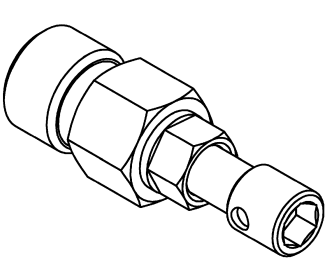
| GENERATOR DECOUPLER TOOL #8433 |
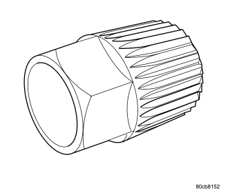
| GENERATOR DECOUPLER TOOL #8823 |