CHIME/BUZZER
DESCRIPTION
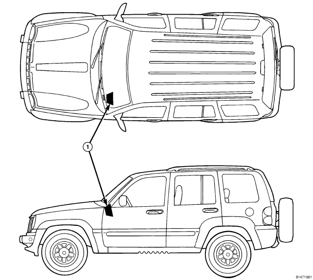
A chime warning system is standard factory-installed equipment. The chime warning system uses an electromechanical transducer that is soldered onto the electronic circuit board inside of the ElectroMechanical Instrument Cluster (EMIC) (1) to provide audible indications of various vehicle conditions that may require the attention of the vehicle operator or occupants.
The electromechanical transducer generates both beep tones and chime tones. The microprocessor-based EMIC utilizes electronic chime request messages received from other modules in the vehicle over the Programmable Communications Interface (PCI) data bus along with hard wired inputs to monitor many sensors and switches throughout the vehicle. In response to those inputs, the circuitry and programming of the EMIC allow it to control the audible outputs that are produced through its on-board transducer.
The EMIC is capable of producing the following audible outputs:
- Fixed Duration Beep - A short, sharp, single tactile beep tone that is about 150 milliseconds in duration.
- Electronic Vehicle Information Center Warning Chime - Two sets of three beep tones indicate a warning is being displayed by the Electronic Vehicle Information Center (EVIC) in the overhead console.
- Single Chime Tone - A single chime tone.
- Slow Rate Repetitive Chime - Repeated chime tones that are issued at a slow rate of about 50 chimes per minute.
- Fast Rate Repetitive Chime - Repeated chime tones that are issued at a fast rate of about 180 chimes per minute.
Hard wired circuitry connects the EMIC and the various chime warning system switch and sensor inputs to their modules and to each other through the electrical system of the vehicle. These hard wired circuits are integral to several wire harnesses, which are routed throughout the vehicle and retained by many different methods. These circuits may be connected to each other, to the vehicle electrical system and to the EMIC through the use of a combination of soldered splices, splice block connectors, and many different types of wire harness terminal connectors and insulators. Refer to the appropriate wiring information. The wiring information includes wiring diagrams, proper wire and connector repair procedures, further details on wire harness routing and retention, as well as pin-out and location views for the various wire harness connectors, splices and grounds.
The EMIC chime warning system circuits and components cannot be adjusted or repaired. If the EMIC circuitry or the on-board transducer are damaged or ineffective, the EMIC unit must be replaced.
OPERATION
The chime warning system operates on battery voltage received through a fuse in the Junction Block (JB) on a non-switched fused B(+) circuit so that the system may operate regardless of the ignition switch position. The chime warning system also monitors the ignition switch position so that some chime features are functional only with the ignition switch in the ON position, while others are functional regardless of the ignition switch position.
The chime warning system provides an audible indication to the vehicle operator or occupants under the following conditions:
- ABS Indicator Warning - On vehicles equipped with an optional Antilock Brake System (ABS), the ElectroMechanical Instrument Cluster (EMIC) transducer will generate one short chime when the ignition switch is in the ON position, and an electronic message is received over the Programmable Communications Interface (PCI) data bus from the Controller Antilock Brake (CAB) requesting ABS indicator illumination. This warning will only occur following completion of the ABS indicator bulb test, and will only occur once during any ignition cycle.
- Airbag Indicator Warning - The EMIC transducer will generate one short chime when the ignition switch is in the ON position, and an electronic message is received over the PCI data bus from the Airbag Control Module (ACM) requesting airbag indicator illumination. This warning will only occur following completion of the airbag indicator bulb test, and will only occur once during any ignition cycle.
- Charging System Indicator Warning - Each time the ignition switch is turned to the ON position, the EMIC transducer will generate a single chime the first time an electronic message is received over the PCI data bus from the Powertrain Control Module (PCM) requesting charging system indicator illumination. This warning indicates that a failure condition has been monitored affecting the operation of the charging system related components or circuits.
- Compass Mini-Trip Computer Global Reset - The EMIC transducer will generate one short chime when the ignition switch is in the ON position, and an electronic message is received over the PCI data bus from the optional Compass Mini-Trip Computer (CMTC) requesting that the CMTC elapsed time, average fuel economy, or trip odometer data be reset. The CMTC monitors hard wired inputs from the US/M (United States/Metric) and RESET button switches, and electronic messages received from the Body Control Module (BCM) to determine the proper electronic reset message to send to the EMIC.
- Door Ajar Warning - On vehicles without an optional Electronic Vehicle Information Center (EVIC), the EMIC transducer will generate one short chime for each of three display sequences when the ignition switch is in the ON position and electronic messages are received over the PCI data bus from the BCM indicating that the status of any door ajar input has changed while the vehicle is moving.
- Electronic Throttle Control Indicator Warning - On vehicles equipped with an optional diesel engine, when the ignition switch is in the ON position the EMIC transducer will generate a single chime the first time an electronic message is received over the PCI data bus from the PCM requesting Electronic Throttle Control (ETC) indicator illumination, either solid or flashing. This chime will only occur once during any ignition cycle.
- Engine Coolant Temperature High Warning - Each time the ignition switch is turned to the ON position, the EMIC transducer will generate chime tones the first time an electronic message is received over the PCI data bus from the PCM indicating that the engine coolant temperature is too high. This chime will sound for five consecutive tones unless an electronic message is received from the PCM indicating that the engine coolant temperature is not too high, or if the ignition switch is turned to the OFF position before the five tones have completed.
- Electronic Stability Program/Brake Assist System Fault Warning - The EMIC transducer will generate one short chime each time the Electronic Stability Program (ESP)/Brake Assist System (BAS) indicator is illuminated in the instrument cluster. This warning indicates a failure condition has been monitored affecting the operation of the ESP/BAS related components or circuits. This warning will only occur following completion of the ESP/BAS indicator bulb test, and will only occur once during any ignition cycle.
- Electronic Vehicle Information Center Warning - On vehicles equipped with an optional EVIC, the EMIC transducer will generate chimes when an electronic message is received over the PCI data bus from the EVIC indicating that the EVIC is displaying certain warnings.
- Fasten Seat Belt Indicator Warning - The EMIC transducer will generate repetitive chimes at a slow rate each time a hard wired input is received from a seat belt switch indicating that the driver or passenger side front seat belt is not fastened with the ignition switch in the ON position. The chime warning system also supports the enhanced seat belt reminder (beltminder) when this feature is enabled, and will sound five chimes at a slow rate (one each time the lamp turns ON during flashing). (Refer to 8 - ELECTRICAL/INSTRUMENT CLUSTER/SEAT BELT INDICATOR - OPERATION).
- Gas Cap Warning - On domestic vehicles equipped with a gasoline engine, the EMIC transducer will generate one short chime each time an electronic message is received over the PCI data bus from the PCM indicating that there is a gross leak in the vapor recovery system. This chime will only occur once during any ignition cycle.
- Gate Ajar Warning - On vehicles without an optional EVIC, the EMIC transducer will generate one short chime for each of three display sequences when the ignition switch is in the ON position, and electronic messages are received over the PCI data bus from the BCM indicating that the status of the tailgate ajar input has changed from closed to not closed while the vehicle is moving.
- Glass Ajar Warning - On vehicles without an optional EVIC, the EMIC transducer will generate one short chime for each of two display sequences when the ignition switch is in the ON position, and electronic messages are received over the PCI data bus from the BCM indicating that the status of the rear flip-up glass ajar input has changed from closed to not closed while the vehicle is moving.
- Head/Park/Fog Lamps-On Warning - The EMIC transducer will generate repetitive chimes at a fast rate when the ignition switch is in any position except ON, and electronic messages are received over the PCI data bus from the BCM indicating that the exterior lamps are ON and that the driver side front door is open. The chimes will continue to sound until the exterior lamps are turned OFF, the driver side front door is closed, or the ignition switch is turned to the ON position, whichever occurs first.
- Key-In-Ignition Warning - The EMIC transducer will generate repetitive chimes at a fast rate when the ignition switch is in any position except ON, and electronic messages are received over the PCI data bus from the BCM indicating that the key is in the ignition lock cylinder and that the driver side front door open. These chimes will continue to sound until the key is removed from the ignition lock cylinder, the driver side front door is closed, or the ignition switch is turned to the ON position, whichever occurs first.
- Low Coolant Warning - On vehicles equipped with an optional diesel engine, the EMIC transducer will generate a single chime when the ignition switch is first turned to the ON position and a hard wired input from the engine coolant level sensor to the EMIC indicates that the coolant level is low for more than about one-quarter of a second. Any time after the ignition switch is first turned to the ON position, the EMIC uses internal programming to check the status of the engine coolant level sensor inputs about once every second, then adjusts an internal counter up or down based upon the status of this input. When the counter accumulates 30 inputs indicating that the coolant level is low, a single chime is sounded. This strategy is intended to reduce the effect that coolant sloshing within the coolant reservoir can have on reliable low coolant warning indications. This chime will only occur once during any ignition cycle.
- Low Fuel Warning - Each time the ignition switch is turned to the ON position, the EMIC transducer will generate a single chime the first time an electronic message is received over the PCI data bus from the PCM requesting low fuel indicator illumination. The chime will only occur a second time during the same ignition cycle if another electronic message has been received from the PCM indicating that there is an increase in the fuel level equal to about 3 liters (0.8 gallon), then a subsequent electronic message from the PCM requests low fuel indicator illumination. This strategy combined with filtering performed by the internal programming of the PCM on the fuel tank sending unit input is intended to reduce the possibility of fuel sloshing within the fuel tank causing multiple low fuel warning chimes during a given ignition cycle. The EMIC will also respond with the low fuel warning chime when electronic fuel level messages are received from the PCM indicating that the hard wired input to the PCM from the fuel tank sending unit is an open circuit (greater than full), or a short circuit (less than empty).
- Low Oil Pressure Indicator Warning - Each time the ignition switch is turned to the ON position, the EMIC transducer will generate a single chime the first time three sequential sets of electronic messages are received over the PCI data bus from the PCM indicating that the engine oil pressure is too low while the engine is running.
- Overspeed Warning - The EMIC transducer will generate repetitive chimes at a slow rate when the ignition switch is in the ON position, and an electronic message is received over the PCI data bus from the PCM indicating that the vehicle speed is over a pre-programmed speed value. These chimes will continue to sound until the vehicle speed messages are below the pre-programmed speed value, or until the ignition switch is turned to the OFF position, whichever occurs first. This feature is only enabled on vehicles that have a BCM that has been configured for sale in a Middle East Gulf Coast Country (GCC).
- No Airbag Indicator Message Warning - The EMIC transducer will generate one short chime and turn ON the airbag indicator when the ignition switch is in the ON position, and an electronic airbag indicator ON or OFF message is not received over the PCI data bus from the ACM for six consecutive seconds.
- No Antilock Brake Indicator Message Warning - The EMIC transducer will generate one short chime and turn ON the ABS indicator when the ignition switch is in the ON position, and an electronic ABS indicator ON or OFF message is not received over the PCI data bus from the CAB for six consecutive seconds.
- No Fuel Level Message Warning - The EMIC transducer will generate one short chime and turn ON the low fuel indicator when the ignition switch is in the ON position, and an electronic fuel level message is not received over the PCI data bus from the PCM for 12 consecutive seconds.
- Remote Keyless Entry Transmitter Programming - On vehicles so equipped, the EMIC transducer will generate a single short chime when an electronic message is received over the PCI data bus from the BCM indicating that a Remote Keyless Entry (RKE) transmitter has been successfully programmed by the customer into the RKE module memory.
- Sentry Key Customer Learn Mode Announcement - On vehicles so equipped, the EMIC transducer will generate one short chime to confirm that the Sentry Key electronic Customer Learn mode is active, which indicates that the Sentry Key REmote Entry Module/Wireless Control Module (SKREEM/WCM) is prepared for programming additional Sentry Key transponders. This chime feature is only active on vehicles equipped with the optional Sentry Key system, and sold in a market where Customer Learn programming is an allowed feature.
- Service Traction Control System Warning - On vehicles so equipped, the EMIC transducer will generate one short chime to confirm that an electronic Service Traction Control System message has been received over the PCI data bus from the CAB to indicate that the traction control system requires service. This warning will only occur once during any ignition cycle.
- Tire Pressure Monitor Warning - The EMIC transducer will generate one short chime when the ignition switch is in the ON position, and an electronic message is received over the PCI data bus from the SKREEM/WCM requesting the Tire Pressure Monitor (TPM) indicator be turned ON for a monitored low tire pressure condition. This warning will only occur once per monitored low tire during any ignition cycle.
- Tire Pressure Monitor Fault Warning - The EMIC transducer will generate one short chime when the ignition switch is in the ON position, and an electronic message is received over the PCI data bus from the SKREEM/WCM requesting the TPM indicator be flashed ON and OFF for a detected TPM sensor or system fault. This warning will only occur once during any ignition cycle.
- Turn Signal On Warning - The EMIC transducer will generate repetitive chimes at a slow rate to indicate that a turn signal has been active continuously for a distance of about 3.2 kilometers (about 2 miles). The chime will continue until the turn signal input becomes inactive, until the hazard warning system is turned ON, or until the ignition switch is turned to the OFF position, whichever occurs first.
- Water-In-Fuel Indicator Warning - On vehicles equipped with a diesel engine, each time the ignition switch is turned to the ON position, the EMIC transducer will generate a single chime the first time an electronic message is received over the PCI data bus from the PCM requesting water-in-fuel indicator illumination. This warning will only occur once during any ignition cycle.
The EMIC provides chime service for all available features in the chime warning system. The EMIC relies upon its internal programming, numerous hard wired inputs, and electronic message inputs received from other modules over the PCI data bus network to provide the chime warning system features. The internal programming of the EMIC determines the priority of each chime request input that is received, as well as the rate and duration of each chime that is to be generated.
The hard wired circuits between components related to the chime warning system may be diagnosed using conventional diagnostic tools and procedures. Refer to the appropriate wiring information. The wiring information includes wiring diagrams, proper wire and connector repair procedures, details of wire harness routing and retention, connector pin-out information and location views for the various wire harness connectors, splices and grounds.
However, conventional diagnostic methods will not prove conclusive in the diagnosis of the chime warning system or the electronic controls or communication between modules and other devices that provide some features of the chime warning system. The most reliable, efficient, and accurate means to diagnose the chime warning system or the electronic controls and communication related to chime warning system operation requires the use of a diagnostic scan tool. Refer to the appropriate diagnostic information.