DIAGNOSIS AND TESTING
- *CHIME INOPERATIVE
- *CHIME SOUNDS WITH DRIVER DOOR OPEN & KEY REMOVED
- *CHIME INOPERATIVE WITH KEY IN IGNITION & DRIVER DOOR OPEN
- *VEHICLE SPEED WARNING CHIME PROBLEM
*CHIME INOPERATIVE
For a complete wiring diagram Refer to Section 8W.
| Possible Causes |
| INSTRUMENT CLUSTER |
Diagnostic Test
1. TEST CHIME OPERATION WITH THE SCAN TOOLTurn the ignition on.
With the scan tool, actuate the Chime.
Does the Chime sound?
Yes
- Refer to the Table of Contents in this Section for related symptoms.
No
- Replace the Instrument Cluster in accordance with the Service Information.
- Perform BODY VERIFICATION TEST - VER 1. (Refer to 8 - ELECTRICAL/ELECTRONIC CONTROL MODULES - STANDARD PROCEDURE).
*CHIME SOUNDS WITH DRIVER DOOR OPEN & KEY REMOVED
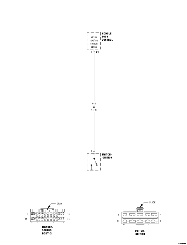
For a complete wiring diagram Refer to Section 8W.
| Possible Causes |
| (G15) KEY-IN IGNITION SWITCH SENSE CIRCUIT SHORTED TO GROUND |
| IGNITION LOCK CYLINDER |
| IGNITION SWITCH |
| BODY CONTROL MODULE (BCM) |
Diagnostic Test
1. CHECK THE KEY IN IGNITION STATUS WITH THE KEY REMOVEDNOTE: Ensure the exterior lamps turn on and off properly and are off before continuing this test.
Turn the ignition on.
With the scan tool in BCM, select Input Output.
Remove the key from the ignition switch.
With the scan tool, read the Key In Ignition status.
Does the scan tool display: Key Not In Ignition?
Yes
- Refer to the Service Information for other possible causes.
- Perform BODY VERIFICATION TEST - VER 1. (Refer to 8 - ELECTRICAL/ELECTRONIC CONTROL MODULES - STANDARD PROCEDURE).
No
- Go To 2
2. CHECK FOR A SHORTED IGNITION LOCK CYLINDER / IGNITION SWITCH
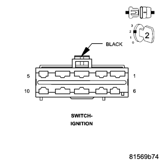
Disconnect the Ignition Switch harness connector.
Does the chime turn off?
Yes
- Inspect the Ignition Lock Cylinder for damage and repair as necessary. If OK, replace the Ignition Switch in accordance with the Service Information.
- Perform BODY VERIFICATION TEST - VER 1. (Refer to 8 - ELECTRICAL/ELECTRONIC CONTROL MODULES - STANDARD PROCEDURE).
No
- Go To 3
3. CHECK THE (G15) KEY-IN IGNITION SWITCH SENSE CIRCUIT FOR A SHORT TO GROUND
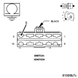
Disconnect the BCM C1 harness connector.
Measure the resistance of the (G15) Key-In Ignition Switch Sense circuit between ground and the Ignition Switch harness connector.
Is the resistance below 100.0 ohms?
Yes
- Repair the (G15) Key-In Ignition Switch Sense circuit for a short to ground.
- Perform BODY VERIFICATION TEST - VER 1. (Refer to 8 - ELECTRICAL/ELECTRONIC CONTROL MODULES - STANDARD PROCEDURE).
No
- Replace and program the BCM in accordance with the Service Information.
- Perform BODY VERIFICATION TEST - VER 1. (Refer to 8 - ELECTRICAL/ELECTRONIC CONTROL MODULES - STANDARD PROCEDURE).
*CHIME INOPERATIVE WITH KEY IN IGNITION & DRIVER DOOR OPEN
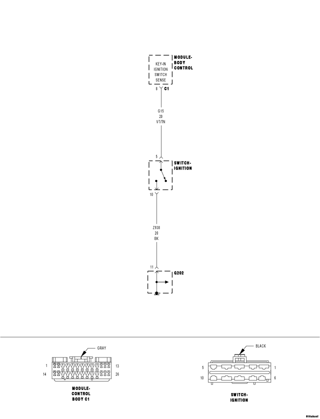
For a complete wiring diagram Refer to Section 8W.
| Possible Causes |
| BODY CONTROL MODULE (BCM) DTC(S) PRESENT |
| (Z938) GROUND CIRCUIT OPEN |
| (G15) KEY-IN IGNITION SWITCH SENSE CIRCUIT OPEN |
| IGNITION SWITCH OPEN |
| BODY CONTROL MODULE (BCM) |
Diagnostic Test
1. CHECK FOR DTCs IN THE BODY CONTROL MODULE (BCM)NOTE: The driver door ajar switch must be operational for the result of this test to be valid.
Turn the ignition on.
With the scan tool, read BCM DTCs.
Does the scan tool display any Cluster Wake Up Output or Communication DTCs?
Yes
- Refer to the Table of Contents in (Refer to 8 - ELECTRICAL/INSTRUMENT CLUSTER - DIAGNOSIS AND TESTING) or in (Refer to 8 - ELECTRICAL/ELECTRONIC CONTROL MODULES - DIAGNOSIS AND TESTING) for the applicable diagnostic procedures.
No
- Go To 2
2. CHECK THE KEY IN IGNITION STATUS WITH THE SCAN TOOL
With the scan tool in BCM, select Input Output.
With the scan tool, read the Key In Ignition Status.
Does the scan tool display: Key In Ignition?
Yes
- Replace and program the BCM in accordance with the Service Information.
- Perform BODY VERIFICATION TEST - VER 1. (Refer to 8 - ELECTRICAL/ELECTRONIC CONTROL MODULES - STANDARD PROCEDURE).
No
- Go To 3
3. CHECK FOR AN OPEN IGNITION SWITCH
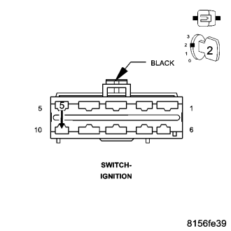
Back probe the Ignition Switch harness connector with a jumper wire between the (G15) Key-In Ignition Switch Sense circuit and the (Z938) Ground circuit.
With the scan tool, read the Key In Ignition Status.
Does the scan tool display: Key In Ignition?
Yes
- Replace the Ignition Switch in accordance with the Service Information.
- Perform BODY VERIFICATION TEST - VER 1. (Refer to 8 - ELECTRICAL/ELECTRONIC CONTROL MODULES - STANDARD PROCEDURE).
No
- Go To 4
4. CHECK THE (Z938) GROUND CIRCUIT FOR AN OPEN
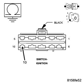
Turn the ignition off.
Remove the jumper wire.
Disconnect the Ignition Switch harness connector.
Turn all lights off.
Measure the resistance of the (Z938) Ground circuit between ground and the Ignition Switch harness connector.
Is the resistance below 5.0 ohms?
Yes
- Go To 5
No
- Repair the (Z938) Ground circuit for an open.
- Perform BODY VERIFICATION TEST - VER 1. (Refer to 8 - ELECTRICAL/ELECTRONIC CONTROL MODULES - STANDARD PROCEDURE).
5. CHECK THE (G15) KEY-IN IGNITION SWITCH SENSE CIRCUIT FOR AN OPEN
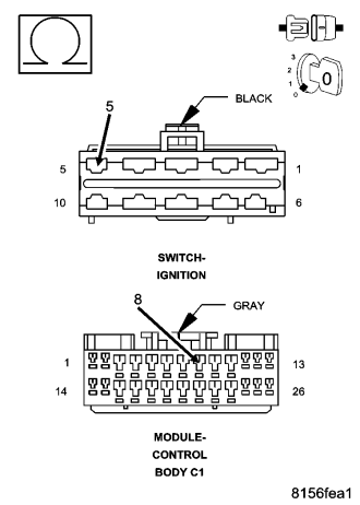
Disconnect the BCM C1 harness connector.
Measure the resistance of the (G15) Key-In Ignition Switch Sense circuit between the Ignition Switch harness connector and the BCM C1 harness connector.
Is the resistance below 5.0 ohms?
Yes
- Replace and program the BCM in accordance with the Service Information.
- Perform BODY VERIFICATION TEST - VER 1. (Refer to 8 - ELECTRICAL/ELECTRONIC CONTROL MODULES - STANDARD PROCEDURE).
No
- Repair the (G15) Key-In Ignition Switch Sense circuit for an open.
- Perform BODY VERIFICATION TEST - VER 1. (Refer to 8 - ELECTRICAL/ELECTRONIC CONTROL MODULES - STANDARD PROCEDURE).
*VEHICLE SPEED WARNING CHIME PROBLEM
For a complete wiring diagram Refer to Section 8W.
| Possible Causes |
| INCORRECT COUNTRY CODE PROGRAMMED IN BODY CONTROL MODULE (BCM) |
| BODY CONTROL MODULE (BCM) |
1. VERIFY THE BCM IS PROGRAMMED WITH THE CORRECT COUNTRY CODE
NOTE: The high speed warning chime is for Gulf Coast Countries only.
Turn the ignition on.
With the scan tool in BCM, select Miscellaneous.
With the scan tool, read the country code setting.
Is the country code incorrect?
Yes
- Reprogram with the correct country code.
- Perform BODY VERIFICATION TEST - VER 1. (Refer to 8 - ELECTRICAL/ELECTRONIC CONTROL MODULES - STANDARD PROCEDURE).
No
- Replace and program the BCM in accordance with the Service Information.
- Perform BODY VERIFICATION TEST - VER 1. (Refer to 8 - ELECTRICAL/ELECTRONIC CONTROL MODULES - STANDARD PROCEDURE).