IGNITION SWITCH
DESCRIPTION
The electrical ignition switch is located on the steering column. It is used as the main on/off switching device for most electrical components. The mechanical key cylinder is used to engage/disengage the electrical ignition switch.
DIAGNOSIS AND TESTING - IGNITION SWITCH
ELECTRICAL DIAGNOSIS
For ignition switch electrical schematics, Refer to the appropriate section for the component.
MECHANICAL DIAGNOSIS (KEY DIFFICULT TO ROTATE)
Vehicles equipped with an automatic transmission and a floor mounted shifter: a cable is used to connect the interlock device in the steering column assembly, to the transmission floor shift lever. This interlock system is used to lock the transmission shifter in the PARK position when the key cylinder is rotated to any position. If the ignition key is difficult to rotate to or from any position, it may not be the fault of the key cylinder or the steering column components. The brake transmission shift interlock cable may be out of adjustment. (Refer to 21 - TRANSMISSION/TRANSAXLE/AUTOMATIC - 30RH/GEAR SHIFT CABLE - ADJUSTMENTS). The interlock system within the steering column is not serviceable. If repair is necessary, the steering column assembly must be replaced. (Refer to 19 - STEERING/COLUMN - REMOVAL).
Vehicles equipped with a manual transmission and a floor mounted shifter: on certain models, a button is located on the steering column behind the ignition key cylinder. The button must be manually depressed to allow rotation of the ignition key cylinder to any position. If it is difficult to rotate the key to any position, the lever mechanism may be defective. This mechanism is not serviceable. If repair is necessary, the steering column assembly must be replaced. (Refer to 19 - STEERING/COLUMN - REMOVAL).
REMOVAL
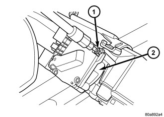
The ignition key must be in the key cylinder for cylinder removal. The key cylinder must be removed first before removing ignition switch.
1. Remove lower steering column cover screws and remove cover.
2. Remove lock cylinder. (Refer to 19 - STEERING/COLUMN/KEY/LOCK CYLINDER - REMOVAL).
3. Remove the multi-function switch.
4. Disconnect the electrical connector at the rear of the ignition switch.
5. Remove the ignition switch mounting screw (1). Use tamper proof torx bit to remove the screw (1).
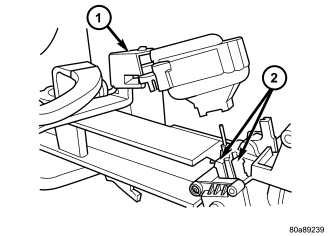
6. Pull the ignition switch (1) straight out to remove from the locking tabs (2).
INSTALLATION
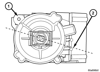
The ignition key must be in the key cylinder for cylinder installation. The key cylinder must be aligned with the ignition switch for installation.
1. Before installing ignition switch (1), rotate the slot in the switch to the ON position (2) .
2. Connect the electrical connector to rear of ignition switch (1). Make sure that locking tab is fully seated into wiring connector.
3. Position the switch to the column and install tamper proof screw. Tighten screw to 2 N·m (17 in. lbs.).
4. Install the lock cylinder (Refer to 19 - STEERING/COLUMN/KEY/LOCK CYLINDER - INSTALLATION).
5. Test the operation of the lock cylinder for smooth rotating.
6. Install the multi-function switch.
7. Install steering column lower cover.