ACTUATOR-BLEND DOOR
DESCRIPTION
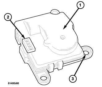
The heating-A/C system uses a reversible, 12-volt direct current (DC) servo motor which mechanically positions the blend-air door. The blend door actuator (1) is located on the top of the HVAC housing.
The blend door actuator is contained within a black molded plastic housing with an integral wire connector receptacle (2) and three integral mounting tabs (3) that allow the actuator to be secured to the HVAC housing. The blend door actuator also has an output shaft with splines that connects it to the linkage that drives the blend-air door. The blend door actuator requires mechanical indexing to the blend door linkage.
OPERATION
The blend door actuator is connected to the A/C-heater control through the vehicle electrical system by a dedicated three-wire lead and connector of the instrument panel wire harness. The blend door actuator can move the blend-air door in two directions. A potentiometer within the actuator allows the A/C-heater control to know the exact position of the blend-air door at all times.
The blend door actuator can be diagnosed using a scan tool. Refer to 9 - Engine Electrical Diagnostics for more information.
The blend door actuator cannot be adjusted or repaired and must be replaced if found inoperative or damaged.
REMOVAL
WARNING: On vehicles equipped with airbags, disable the airbag system before attempting any steering wheel, steering column, or instrument panel component diagnosis or service. Disconnect and isolate the negative battery (ground) cable, then wait two minutes for the airbag system capacitor to discharge before performing further diagnosis or service. This is the only sure way to disable the airbag system. Failure to take the proper precautions could result in accidental airbag deployment and possible personal injury or death.
NOTE: Prior to performing this procedure, turn the ignition key to ON and set the A/C-heater control in the mid-temperature position and wait 10 seconds.
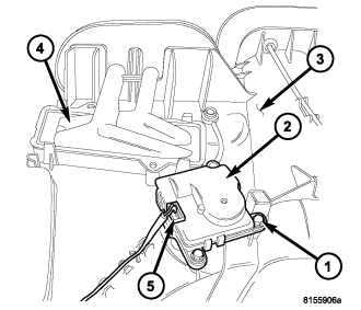
NOTE: LHD model shown. RHD model similar.
1. Remove the instrument panel from the vehicle (refer to 23 - BODY/INSTRUMENT PANEL - REMOVAL).
2. Remove the three screws (1) that secure the blend door actuator (2) to the top of the HVAC housing (3) near the heater core (4).
NOTE: Note the actuator shaft position for installation reference.
3. Remove the blend door actuator from the HVAC housing and disconnect the wire harness connector (5) from the actuator.
4. Remove the blend door actuator from the vehicle.
INSTALLATION
NOTE: LHD model shown. RHD model similar.
1. Position the blend door actuator (2) onto the top of the HVAC housing (3) near the heater core (4), making sure the actuator spline is positioned properly with the door spline. If necessary, rotate the actuator slightly to align the splines on the actuator output shaft with those on the blend door pivot.
2. Install the three screws (1) that secure the blend door actuator to the HVAC housing. Tighten the screws to 2 N·m (17 in. lbs.).
3. Connect the wire harness connector (5) to the blend door actuator.
4. Install the instrument panel (refer to 23 - BODY/INSTRUMENT PANEL - INSTALLATION).