VALVE-VACUUM CHECK
DESCRIPTION
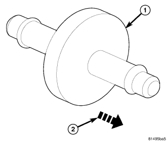
Both the heating-A/C system and the heater-only system use two vacuum check valves. One vacuum check valve (1) is installed in the accessory vacuum supply line located on the dash panel in the engine compartment, near the brake booster and, the other check valve is located on the passenger side of the HVAC housing, behind the glove box. The vacuum check valves are used to stabilize the vacuum within the HVAC vacuum circuits whenever the vehicle is accelerating or when engine vacuum varies due to operating conditions. The vacuum check valves are designed to allow vacuum to flow in only one direction (2) through the vacuum supply circuits.
OPERATION
The use of two vacuum check valves help to maintain the vacuum required to retain the heating and the A/C systems in the selected operating mode. The vacuum check valves will prevent the engine from bleeding down system vacuum through the intake manifold during extended heavy engine load (low engine vacuum) operation.
The vacuum check valves cannot be repaired and must be replaced if found inoperative or damaged.
REMOVAL
NOTE: Make note the orientation of the vacuum check valves in the vacuum supply circuit for correct installation position.
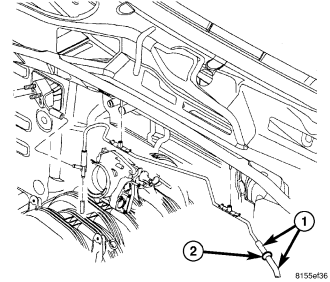
NOTE: LHD 3.7L engine shown. Diesel and RHD models similar.
1. Disconnect the vacuum supply line connectors (1) from the vacuum check valve (2) located in the engine compartment near the dash panel and remove the valve.
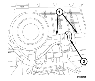
NOTE: LHD heating-A/C system shown. RHD similar.
2. Disconnect the vacuum supply line connectors from the vacuum check valve located in the passenger compartment, behind the glove box and remove the valve.
INSTALLATION
NOTE: Be sure to install the vacuum check valves into the vacuum supply circuit in the correct orientation as noted during removal.
NOTE: LHD heating-A/C system shown. RHD similar.
1. Position the vacuum check valve (2) into the passenger compartment behind the glove box and connect the vacuum supply line connectors (1) to the check valve.
NOTE: LHD 3.7L engine shown. Diesel and RHD models similar.
2. Position the vacuum check valve (2) into the engine compartment near the dash panel and connect the vacuum supply line connectors (1) to the check valve.