A/C PRESSURE SENSOR LOW (BCM)
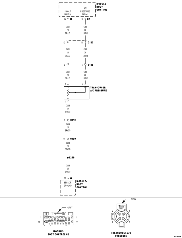
For a complete wiring diagram Refer to Section 8W.
- When Monitored:
With the ignition on.
- Set Condition:
The Body Control Module (BCM) will set this DTC if voltage drops below 0.137 volts for more than 5 seconds on the (C18) A/C Pressure Sensor Signal circuit.
| Possible Causes |
| (C18) A/C PRESSURE SIGNAL CIRCUIT SHORTED TO GROUND |
| (C18) A/C PRESSURE SIGNAL CIRCUIT SHORTED TO THE (K310) SENSOR GROUND CIRCUIT |
| (K301) 5-VOLT SUPPLY CIRCUIT OPEN |
| (K301) 5-VOLT SUPPLY CIRCUIT SHORTED TO GROUND |
| (K301) 5-VOLT SUPPLY CIRCUIT SHORTED TO THE (K310) SENSOR GROUND CIRCUIT |
| A/C PRESSURE TRANSDUCER |
| BCM |
Diagnostic Test
1. CHECK THE A/C PRESSURE TRANSDUCER VOLTAGENOTE: Verify that the A/C Refrigerant System is properly charged before proceeding.
Start the engine.
With the scan tool, read the A/C Pressure Transducer voltage.
Is the voltage below 0.5 volts?
Yes
- Go To 2
No
- Go To 9
2. CHECK THE (K301) 5-VOLT SUPPLY CIRCUIT VOLTAGE
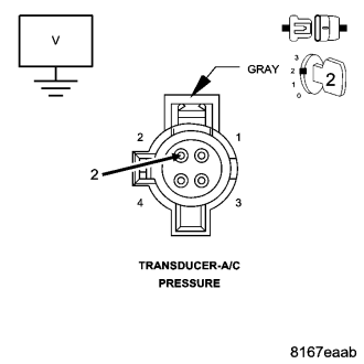
Turn the ignition off.
Disconnect the A/C Pressure Transducer harness connector.
Turn the ignition on.
Measure the voltage of the (K301) 5-Volt Supply circuit.
Is the voltage above 4.5 volts?
Yes
- Go To 3
No
- Go To 6
3. CHECK THE A/C PRESSURE TRANSDUCER VOLTAGE WITH THE TRANSDUCER DISCONNECTED
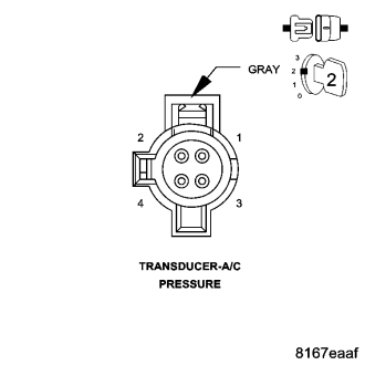
With the scan tool, read the A/C Pressure Transducer voltage.
Is the voltage above 0.5 of a volt?
Yes
- Replace the A/C Pressure Transducer in accordance with the Service Information.
- Perform BODY VERIFICATION TEST - VER 1. (Refer to 8 - ELECTRICAL/ELECTRONIC CONTROL MODULES - STANDARD PROCEDURE).
No
- Go To 4
4. CHECK THE (C18) A/C PRESSURE SIGNAL CIRCUIT FOR A SHORT TO GROUND
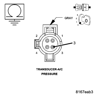
Turn the ignition off.
Disconnect the BCM C2 harness connector.
Measure the resistance between ground and the (C18) A/C Pressure Signal circuit at the A/C Pressure Transducer harness connector.
Is the resistance below 10k ohms?
Yes
- Repair the (C18) A/C Pressure Signal circuit for a short to ground.
- Perform BODY VERIFICATION TEST - VER 1. (Refer to 8 - ELECTRICAL/ELECTRONIC CONTROL MODULES - STANDARD PROCEDURE).
No
- Go To 5
5. CHECK THE (C18) A/C PRESSURE SIGNAL CIRCUIT FOR A SHORT TO THE (K310) SENSOR GROUND CIRCUIT
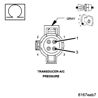
Measure the resistance between the (C18) A/C Pressure Signal circuit and the (K310) Sensor Ground circuit at the A/C Pressure Transducer harness connector.
Is the resistance below 10k ohms?
Yes
- Repair the (C18) A/C Pressure Signal circuit for a short to the (K310) Sensor Ground circuit.
- Perform BODY VERIFICATION TEST - VER 1. (Refer to 8 - ELECTRICAL/ELECTRONIC CONTROL MODULES - STANDARD PROCEDURE).
No
- Replace and program the BCM in accordance with the Service Information.
- Perform BODY VERIFICATION TEST - VER 1. (Refer to 8 - ELECTRICAL/ELECTRONIC CONTROL MODULES - STANDARD PROCEDURE).
6. CHECK THE (K301) 5-VOLT SUPPLY CIRCUIT FOR AN OPEN
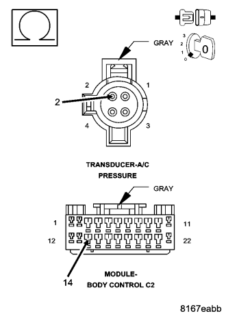
Turn the ignition off.
Disconnect the BCM C2 harness connector.
Measure the resistance of the (K301) 5-Volt Supply circuit between the A/C Pressure Transducer harness connector and the BCM C2 harness connector.
Is the resistance below 5.0 ohms?
Yes
- Go To 7
No
- Repair the (K301) 5-Volt Supply circuit for an open.
- Perform BODY VERIFICATION TEST - VER 1. (Refer to 8 - ELECTRICAL/ELECTRONIC CONTROL MODULES - STANDARD PROCEDURE).
7. CHECK THE (K301) 5-VOLT SUPPLY CIRCUIT FOR A SHORT TO GROUND
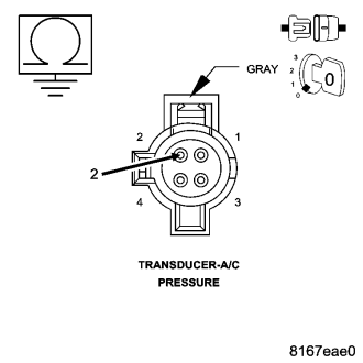
Measure the resistance between ground and the (K301) 5-Volt Supply circuit at the A/C Pressure Transducer harness connector.
Is the resistance below 10k ohms?
Yes
- Repair the (K301) 5-Volt Supply circuit for a short to ground.
- Perform BODY VERIFICATION TEST - VER 1. (Refer to 8 - ELECTRICAL/ELECTRONIC CONTROL MODULES - STANDARD PROCEDURE).
No
- Go To 8
8. CHECK THE (K301) 5-VOLT SUPPLY CIRCUIT FOR A SHORT TO FOR A SHORT TO THE (K310) SENSOR GROUND CIRCUIT
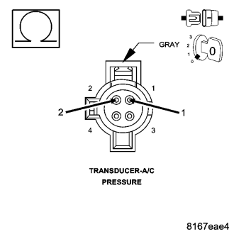
Measure the resistance between the (K301) 5-Volt Supply circuit and the (K310) Sensor Ground circuit at the A/C Pressure Transducer harness connector.
Is the resistance below 10k ohms?
Yes
- Repair the (K301) 5-Volt Supply circuit for a short to the (K310) Sensor Ground circuit.
- Perform BODY VERIFICATION TEST - VER 1. (Refer to 8 - ELECTRICAL/ELECTRONIC CONTROL MODULES - STANDARD PROCEDURE).
No
- Replace and program the BCM in accordance with the Service Information.
- Perform BODY VERIFICATION TEST - VER 1. (Refer to 8 - ELECTRICAL/ELECTRONIC CONTROL MODULES - STANDARD PROCEDURE).
9. TEST FOR INTERMITTENT CONDITION
NOTE: The condition that set this DTC is not present at this time. The following may help in identifying the cause of the intermittent condition.
Check the Technical Service Bulletins (TSBs) for related concerns.
Turn the ignition on.
Using the scan tool, erase the BCM DTCs.
Turn the ignition off, wait 10 seconds, then turn the ignition on.
Monitor the scan tool for DTCs while wiggling the related wiring harness.
Turn the ignition off.
Using the wiring diagram/schematic as a guide, inspect the related wiring and connectors for chaffed, pierced, pinched, and partially broken wires, and for broken, bent, pushed out, corroded, and contaminated terminals. Repair as necessary.
Perform a voltage drop test on the related circuits between the component and the BCM.
If numerous DTCs were set, use the wiring diagram/schematic to check for common ground and supply circuits.
Were any problems found?
Yes
- Repair as necessary.
- Perform BODY VERIFICATION TEST - VER 1. (Refer to 8 - ELECTRICAL/ELECTRONIC CONTROL MODULES - STANDARD PROCEDURE).
No
- Test Complete.