*NO RESPONSE FROM RADIO
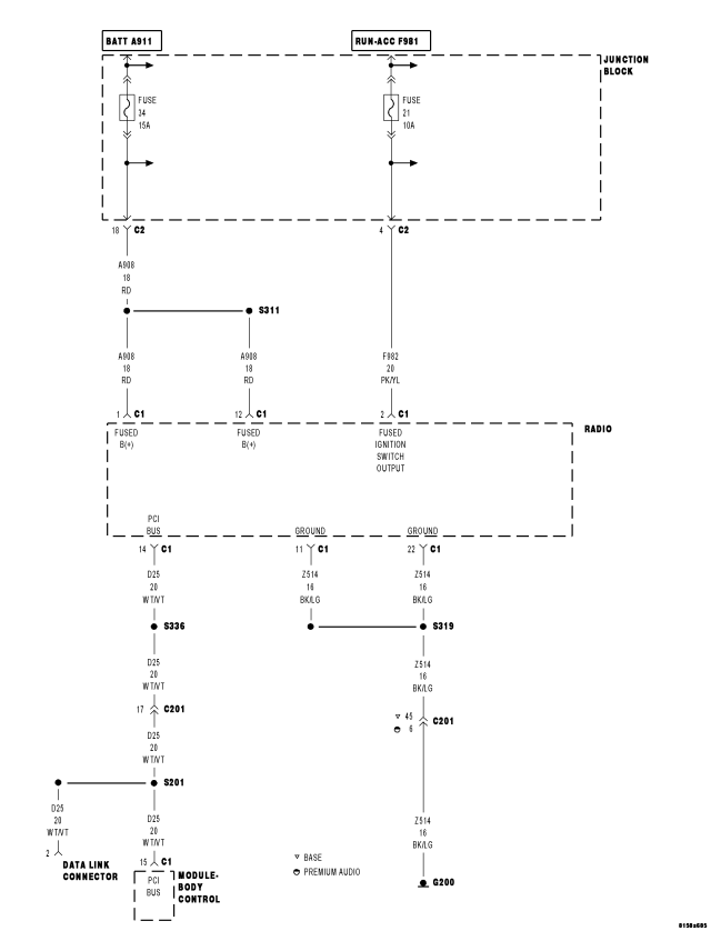
For a complete wiring diagram Refer to Section 8W.
| Possible Causes |
| (Z514) GROUND CIRCUIT OPEN |
| (A908) FUSED B(+) CIRCUIT OPEN |
| (F982) FUSED IGNITION SWITCH OUTPUT CIRCUIT OPEN |
| (D25) PCI BUS CIRCUIT OPEN |
| RADIO |
Diagnostic Test
1. TEST FOR INTERMITTENT CONDITIONTurn the ignition on.
NOTE: Ensure the IOD fuse is installed and battery voltage is between 10.0 and 16.0 volts.
With the scan tool, select ECU view.
NOTE: A red X will be next to the module that is not communicating, indicating that the module is not active on the Bus network. A green check indicates that the module is active on the Bus network.
Does the scan tool display a red X next to the module?
Yes
- Go To 2
No
- The no response condition is not present at this time. Using the wiring diagram/schematic as a guide, inspect the wiring for chafed, pierced, pinched, and partially broken wires and the wiring harness connectors for broken, bent, pushed out, and corroded terminals.
2. (Z514) GROUND CIRCUIT OPEN
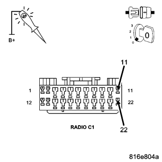
Turn the ignition off.
Disconnect the Radio C1 harness connector.
Using a 12-volt test light connected to 12-volts, probe each (Z514) ground circuit.
Does the test light illuminate brightly for each circuit?
Yes
- Go To 3
No
- Repair the (Z514) Ground circuit for an open.
- Perform BODY VERIFICATION TEST – VER 1. (Refer to 8 - ELECTRICAL/ELECTRONIC CONTROL MODULES - STANDARD PROCEDURE).
3. (A908) FUSED B(+) CIRCUIT OPEN
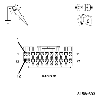
Using a 12-volt test light connected to ground, probe each (A908) Fused B(+) circuit.
Does the test light illuminate brightly for each circuit?
Yes
- Go To 4
No
- Repair the (A908) Fused B(+) circuit for an open.
- Perform BODY VERIFICATION TEST – VER 1. (Refer to 8 - ELECTRICAL/ELECTRONIC CONTROL MODULES - STANDARD PROCEDURE).
4. (F982) FUSED IGNITION SWITCH OUTPUT CIRCUIT OPEN
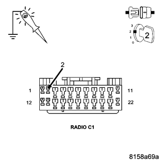
Turn the ignition on.
Using a 12-volt test light connected to ground, probe the (F982) Fused Ignition Switch Output circuit.
Does the test light illuminate brightly?
Yes
- Go To 5
No
- Repair the (F982) Fused Ignition Switch Output circuit for an open.
- Perform BODY VERIFICATION TEST – VER 1. (Refer to 8 - ELECTRICAL/ELECTRONIC CONTROL MODULES - STANDARD PROCEDURE).
5. (D25) PCI BUS CIRCUIT OPEN
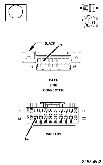
Turn the ignition off.
Disconnect the scan tool from the DLC connector.
Measure the resistance of the (D25) PCI Bus circuit between the DLC and the Radio C1 connector.
Is the resistance below 5.0 ohms?
Yes
- Replace the Radio in accordance with the service information.
- Perform BODY VERIFICATION TEST – VER 1. (Refer to 8 - ELECTRICAL/ELECTRONIC CONTROL MODULES - STANDARD PROCEDURE).
No
- Repair the (D25) PCI Bus circuit for an open.
- Perform BODY VERIFICATION TEST – VER 1. (Refer to 8 - ELECTRICAL/ELECTRONIC CONTROL MODULES - STANDARD PROCEDURE).