*CAN C BUS COMMUNICATION FAILURE
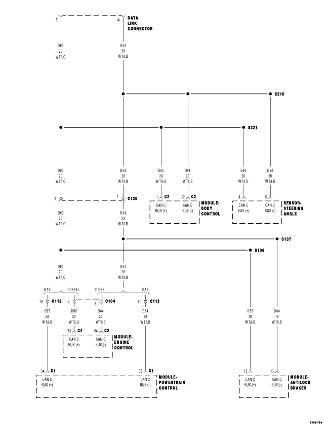
For a complete wiring diagram Refer to Section 8W.
- When Monitored:
With the ignition on.
- Set Condition:
The scan tool cannot communicate with ANY module on the CAN C Bus circuit.
| Possible Causes |
| (D65) CAN C BUS (+) CIRCUIT SHORTED TO VOLTAGE |
| (D64) CAN C BUS (-) CIRCUIT SHORTED TO VOLTAGE |
| (D65) CAN C BUS (+) CIRCUIT SHORTED TO GROUND |
| (D64) CAN C BUS (-) CIRCUIT SHORTED TO GROUND |
| (D65) CAN C BUS (+) CIRCUIT SHORTED TO (D64) CAN C BUS (-) CIRCUIT |
| ANTILOCK BRAKE MODULE |
| POWERTRAIN CONTROL MODULE (PCM or ECM) |
| STEERING ANGLE SENSOR |
| BODY CONTROL MODULE |
Diagnostic Test
1. VERIFY CAN C BUS COMMUNICATIONTurn the ignition on.
NOTE: Ensure the IOD fuse is installed and battery voltage is between 10.0 and 16.0 volts.
With the scan tool select ECU View.
NOTE: A red X will be next to the module that is not communicating or not installed on the vehicle, indicating that the module is not active on the Bus network. A green check indicates that the module is active on the Bus network.
Does the scan tool communicate with any module on the CAN C Bus circuit?
Yes
- The conditions that caused this symptom are not present at this time. Using the wiring diagram/schematic as a guide, inspect the wiring and connectors.
No
- Go To 2
2. CHECK THE D65 CAN C (+) AND (D64) CAN C (-) CIRCUITS FOR A SHORT TO VOLTAGE
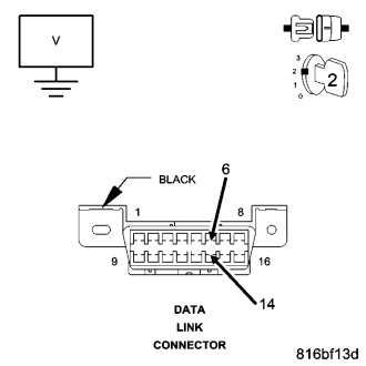
Turn the ignition on.
Measure the voltage of the (D65) CAN C Bus (+) circuit and the (D64) CAN C Bus (-) circuit at the DLC.
Is the voltage steadily above 4.0 volts?
Yes
- Go To 3
No
- Go To 4
3. (D65) CAN C BUS (+) CIRCUIT OR (D64) CAN C BUS (-) CIRCUIT SHORTED TO VOLTAGE
Turn the ignition off.
Disconnect the scan tool from the DLC.
NOTE: Perform the following steps for each module on the CAN C Bus Circuit.
Measure the voltage between the (D65) CAN C Bus (+) circuit and the (D64) CAN C Bus (-) circuit and ground at the DLC.
Disconnect a module, turn the ignition on and check if the module that was disconnected was causing the short to voltage internally.
While monitoring the voltmeter, disconnect each module on the CAN C Bus Circuit one at a time.
Is there any voltage present with all modules disconnected?
Yes
- Repair the (D65) CAN C Bus (+) circuit or (D64) CAN C Bus (-) circuit for a short to voltage.
- Perform BODY VERIFICATION TEST - VER 1. (Refer to 8 - ELECTRICAL/ELECTRONIC CONTROL MODULES - STANDARD PROCEDURE)
No
- Replace the module in accordance with the service information that when disconnected eliminated the short to voltage.
- Perform BODY VERIFICATION TEST - VER 1. (Refer to 8 - ELECTRICAL/ELECTRONIC CONTROL MODULES - STANDARD PROCEDURE)
4. CHECK THE (D65) CAN C BUS (+) CIRCUIT AND THE (D64) CAN C BUS (-) CIRCUIT FOR A SHORT TO GROUND
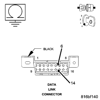
Turn the ignition off.
Measure the resistance between the (D65) CAN C Bus (+) circuit and ground and the (D64) CAN C Bus (-) circuit and ground at the DLC.
Is the resistance below 5.0 ohms on either circuit?
Yes
- Go To 5
No
- Go To 6
5. (D65) CAN C BUS (+) CIRCUIT OR (D64) CAN C (-) CIRCUIT SHORTED TO GROUND
Turn the ignition off.
NOTE: Perform the following steps for each module on the CAN C Bus Circuit.
Measure the resistance between the (D65) CAN C Bus (+) circuit and the (D64) CAN C Bus (-) circuit and ground at the DLC.
Disconnect a module, check if the module that was disconnected was causing the short to ground internally.
While monitoring the ohmmeter, disconnect each module on the CAN C Bus Circuit one at a time.
Is the resistance below 5.0 ohms with all modules disconnected?
Yes
- Repair the (D65) CAN C Bus (+) circuit or (D64) CAN C Bus (-) circuit for a short to ground.
- Perform BODY VERIFICATION TEST - VER 1. (Refer to 8 - ELECTRICAL/ELECTRONIC CONTROL MODULES - STANDARD PROCEDURE)
No
- Replace the module in accordance with the service information that when disconnected eliminated the short to ground.
- Perform BODY VERIFICATION TEST - VER 1. (Refer to 8 - ELECTRICAL/ELECTRONIC CONTROL MODULES - STANDARD PROCEDURE)
6. (D65) CAN C BUS (+) CIRCUIT SHORTED TO (D64) CAN C BUS (-) CIRCUIT
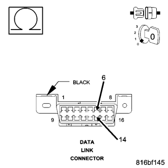
NOTE: Perform the following steps for each module on the CAN C Bus Circuit.
Measure the resistance between the (D65) CAN C Bus (+) circuit and the (D64) CAN C Bus (-) circuit at the DLC.
Disconnect a module, check if the module that was disconnected was causing the short internally.
While monitoring the ohmmeter, disconnect each module on the CAN C Bus Circuit one at a time.
Is the resistance below 5.0 ohms with all modules disconnected?
Yes
- Repair the (D65) CAN C Bus (+) circuit for a short to the (D64) CAN C Bus (-) circuit.
- Perform BODY VERIFICATION TEST - VER 1. (Refer to 8 - ELECTRICAL/ELECTRONIC CONTROL MODULES - STANDARD PROCEDURE)
No
- Replace the module in accordance with the service information that when disconnected eliminated the short.
- Perform BODY VERIFICATION TEST - VER 1. (Refer to 8 - ELECTRICAL/ELECTRONIC CONTROL MODULES - STANDARD PROCEDURE)