*PCI BUS COMMUNICATION FAILURE
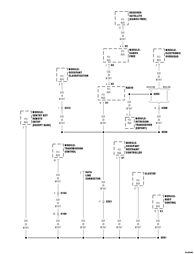
For a complete wiring diagram Refer to Section 8W.
| Possible Causes |
| (D25) PCI BUS CIRCUIT OPEN AT DATA LINK CONNECTOR (DLC) |
| (D25) PCI BUS CIRCUIT SHORTED TO GROUND |
| (D25) PCI BUS CIRCUIT SHORTED TO VOLTAGE |
| ANY PCI BUS MODULE INTERNALLY SHORTED TO GROUND |
| ANY PCI BUS MODULE INTERNALLY SHORTED TO VOLTAGE |
Diagnostic Test
1. PCI BUS COMMUNICATION AND TEST FOR INTERMITTENT CONDITIONTurn the ignition on.
NOTE: Ensure the IOD fuse is installed and battery voltage is between 10.0 and 16.0 volts.
With the scan tool, select ECU view.
NOTE: A red X will be next to the module that is not communicating or not installed on the vehicle, indicating that the module is not active on the Bus network. A green check indicates that the module is active on the Bus network.
Does the scan tool communicate with any module on the PCI Bus network?
Yes
- The conditions that caused this symptom are not present at this time. Using the wiring diagram/schematic as a guide, inspect the wiring and connectors.
No
- Go To 2
2. (D25) PCI BUS CIRCUIT OPEN AT THE DLC
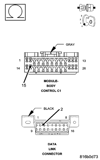
NOTE: If the PCI Bus circuit is open between the BCM and the DLC the scan tool will be unable to identify the vehicle. Perform the test below to determine if the open condition exists causing the scan tool error.
Turn the ignition off.
Disconnect the negative battery cable.
Disconnect the scan tool from the DLC.
Disconnect the BCM C1 harness connector.
Measure the resistance of the (D25) PCI Bus circuit between the DLC and the BCM harness connector.
Is the resistance below 5.0 ohms?
Yes
- Go To 3
No
- Repair the (D25) PCI Bus circuit for an open.
- Perform BODY VERIFICATION TEST – VER 1. (Refer to 8 - ELECTRICAL/ELECTRONIC CONTROL MODULES - STANDARD PROCEDURE).
3. CHECK THE (D25) PCI BUS CIRCUIT FOR A SHORT TO VOLTAGE
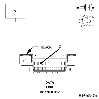
NOTE: Reconnect the BCM harness connector and the negative battery cable.
Turn the ignition on.
Measure the voltage of the (D25) PCI Bus circuit at the DLC.
Is the voltage steadily above 7.0 volts?
Yes
- Go To 4
No
- Go To 5
4. (D25) PCI BUS CIRCUIT SHORTED TO VOLTAGE
NOTE: If the PCI Bus circuit is shorted to voltage the scan tool will be unable to identify the vehicle. Perform the test below, make the repairs as indicated. Re-attempt communication with the scan tool.
Turn the ignition off.
Using a voltmeter, connect one end to the (D25) PCI Bus circuit at the DLC and the other end to ground.
NOTE: For each module on the PCI Bus perform the following steps.
Turn the ignition off, wait one minute before disconnecting a module, turn the ignition on and check if the module disconnected was causing the short to voltage internally.
While monitoring the voltmeter, disconnect each module the vehicle is equipped with one at a time.
Is the voltage steadily above 7.0 volts with all the modules disconnected?
Yes
- Repair the (D25) PCI Bus circuit for a short to voltage.
- Perform BODY VERIFICATION TEST – VER 1. (Refer to 8 - ELECTRICAL/ELECTRONIC CONTROL MODULES - STANDARD PROCEDURE).
No
- Replace the module that when disconnected eliminated the short to voltage.
- Perform BODY VERIFICATION TEST – VER 1. (Refer to 8 - ELECTRICAL/ELECTRONIC CONTROL MODULES - STANDARD PROCEDURE).
5. (D25) PCI BUS CIRCUIT SHORTED TO GROUND
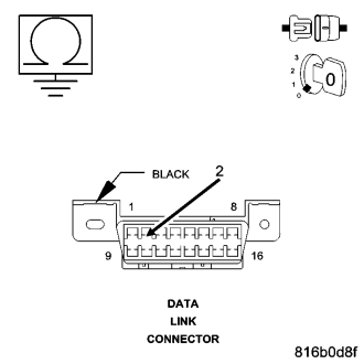
NOTE: If the PCI Bus circuit is shorted to ground the scan tool will be unable to identify the vehicle. Perform the test below, make the repairs as indicated. When the repair is complete unplug the IOD fuse, wait 30 seconds, and plug the fuse back in. This will re-initialize the BCM. Re-attempt communication with the scan tool.
Turn the ignition off.
Using a ohmmeter, connect one end to the (D25) PCI Bus circuit at the DLC and the other end to ground.
While monitoring the ohmmeter, disconnect each module the vehicle is equipped with one at a time.
NOTE: Total bus resistance to ground thru all of the modules is typically between 350 to 1000 ohms. The more modules on the PCI Bus, the lower the total resistance will be.
Is the resistance below 150.0 ohms with all the modules disconnected?
Yes
- Repair the (D25) PCI Bus circuit for a short to ground.
- Perform BODY VERIFICATION TEST – VER 1. (Refer to 8 - ELECTRICAL/ELECTRONIC CONTROL MODULES - STANDARD PROCEDURE).
No
- Replace the module that when disconnected the short to ground was eliminated.
- Perform BODY VERIFICATION TEST – VER 1. (Refer to 8 - ELECTRICAL/ELECTRONIC CONTROL MODULES - STANDARD PROCEDURE).