MODULE-HEATED SEAT
DESCRIPTION
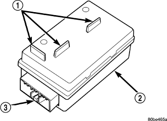
The heated seat module (2) is also known as the Seat Heat Interface Module. The heated seat module (2) is located under the left front seat cushion, where it is secured to a mounting bracket via two push-pin retainers. The heated seat module has a single connector receptacle (3) that allows the module to be connected to all of the required inputs and outputs through the seat wire harness.
The heated seat module (2) is an electronic microprocessor controlled device designed and programmed to use inputs from the heated seat relay, the two heated seat switches and the two heated seat sensors to operate and control the heated seat elements in both front seats and the two heated seat indicator lamp Light-Emitting Diodes (LEDs) in each heated seat switch. The heated seat module is also programmed to perform self-diagnosis of certain heated seat system functions and provide feedback of that diagnosis through the heated seat switch indicator lamps.
The heated seat module (2) cannot be repaired. If the heated seat module is damaged or faulty, the entire module must be replaced.
OPERATION
The heated seat module operates on fused battery current received from a fuse in the junction block. The module is grounded at all times. Inputs to the module include a resistor multiplexed heated seat switch request circuit for each of the two heated seat switches and the heated seat sensor inputs from the seat cushions of each front seat. In response to those inputs, the heated seat module controls battery current to the heated seat elements and sensors, and controls the ground for the heated seat switch indicator lamps (LED's).
When a heated seat switch (Driver or Passenger) is depressed a signal is received by the heated seat module, the module energizes the proper indicator LED (Low or High) in the switch by grounding the indicator lamp circuit to indicate that the heated seat system is operating. At the same time, the heated seat module energizes the selected heated seat sensor circuit and the sensor provides the module with an input indicating the surface temperature of the selected seat cushion.
The Low heat set point is about 36° C (96.8° F), and the High heat set point is about 42° C (107.6° F). If the seat cushion surface temperature input is below the temperature set point for the selected temperature setting, the heated seat module energizes an N-channel Field Effect Transistor (N-FET) within the module which energizes the heated seat elements in the selected seat cushion and back. When the sensor input to the module indicates the correct temperature set point has been achieved, the module de-energizes the N-FET which de-energizes the heated seat elements. The heated seat module will continue to cycle the N-FET as needed to maintain the selected temperature set point.
If the heated seat module detects a heated seat sensor value input that is out of range or a shorted or open heated seat element circuit, it will notify the vehicle operator or the repair technician of this condition by flashing the High and/or Low indicator lamps in the affected heated seat switch. Refer to Diagnosis and Testing Heated Seat System in Heated Systems for flashing LED diagnosis and testing procedures. Refer to Diagnosis and Testing Heated Seat Module in this section for heated seat module diagnosis and testing procedures. Also refer to the Body Diagnostic Manual for additional diagnosis and testing procedures.
DIAGNOSIS AND TESTING - HEATED SEAT MODULE
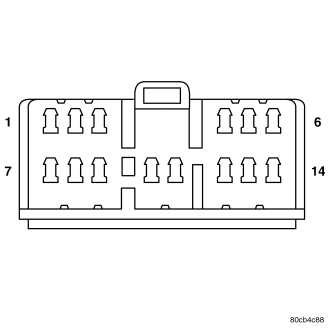
If a heated seat fails to heat and one or both of the indicator lamps on a heated seat switch flash, refer to Heated Seat System Diagnosis and Testing in Heated Systems for flashing LED failure identification. Refer to Wiring Diagrams in for complete heated seat system wiring diagrams.
1. Remove the heated seat module from its mounting location (Refer to 8 - ELECTRICAL/ELECTRONIC CONTROL MODULES/MEMORY HEATED SEAT/MIRROR MODULE - REMOVAL).
NOTE: Any resistance values (ohms Ω) given in the following text are supplied using the automatic range generated by a fluke® automotive meter. If another type of measuring device is used the values generated may not be the same as the results shown here, or may have to be converted to the range used here.
RIGHT SEAT HEATER INOPERATIVE
1. If a heated seat heats but one or both indicator lamps (LED's) on the heated seat switch fail to illuminate, check the driver circuit with the inoperative LED for a short to ground. If OK, replace the heated seat switch. If NOT OK repair the short to ground as required and than replace the heated seat switch.
NOTE: If the right seat cushion is already warm the following step will not prove conclusive.
2. Back-probe the heated seat module wire harness connector, do not disconnect. Check cavity #3 for battery voltage when the right heated seat switch is turned “ON”, voltage should be present, If OK go to STEP 3 If NOT OK, test the right heated seat switch (Refer to 8 - ELECTRICAL/HEATED SEATS/PASSENGER HEATED SEAT SWITCH - DIAGNOSIS AND TESTING). If the switch tests OK, check for continuity between the switch and control module on the MUX circuit, If OK replace the heated seat control module. If NOT OK, repair the open or shorted MUX circuit as required.
NOTE: Be certain the battery is fully charged before testing. Failure to do so can result in incorrect readings.
3. Back-probe the heated seat module wire harness connector, do not disconnect. Check cavity #10 for battery voltage, while observing the voltmeter depress the right heated seat switch low setting twice, voltage should toggle between approx.12v and 8v, If OK go to STEP 4. If NOT OK check for continuity between the switch and control module on the low heat driver circuit, If OK replace the heated seat control module.
4. Back-probe the heated seat module wire harness connector, do not disconnect. Check cavity #11 for battery voltage, while observing the voltmeter depress the right heated seat switch high setting twice, voltage should toggle between approx.12v and 8v, If OK go to STEP 5. If NOT OK check for continuity between the switch and control module on the high heat driver circuit, If OK replace the heated seat control module.
5. Back-probe the heated seat module wire harness connector, do not disconnect. Check cavity #2 for approx. 5v, voltage should be present, If OK go to STEP 6. If NOT OK replace the heated seat control module.
6. Back-probe the heated seat module wire harness connector, do not disconnect. Check cavity #7 for a range in voltage from 1.72v (warm seat) – 3.0v (cold seat). It should be within this range, If OK replace the heated seat module. If NOT OK test the Heated Seat Sensor. If NOT OK, replace the right heated seat element and sensor assembly. If the heated seat sensor tests OK, check for continuity between the right heated seat cushion connector and control module connector on the 5v supply circuit, If NOT OK, repair the open or shorted 5v supply circuit as required. If OK check for continuity between the right heated seat cushion connector and control module connector on the temperature sensor input circuit. If NOT OK, repair the open or shorted temperature sensor input circuit as required. If OK replace the heated seat control module.
LEFT SEAT HEATER INOPERATIVE
1. If a heated seat heats but one or both indicator lamps (LED's) on the heated seat switch fail to illuminate, check the driver circuit with the inoperative LED for a short to ground. If OK, replace the heated seat switch. If NOT OK repair the short to ground as required and than replace the heated seat switch.
NOTE: If the left seat cushion is already warm the following step will not prove conclusive.
2. Back-probe the heated seat module wire harness connector, do not disconnect. Check cavity #5 for battery voltage when the left heated seat switch is turned “ON”, voltage should be present, If OK go to STEP 3 If NOT OK, test the left heated seat switch (Refer to 8 - ELECTRICAL/HEATED SEATS/DRIVER HEATED SEAT SWITCH - DIAGNOSIS AND TESTING). If the switch tests OK, check for continuity between the switch and control module on the MUX circuit, If OK replace the heated seat control module. If NOT OK, repair the open or shorted MUX circuit as required.
3. Back-probe the heated seat module wire harness connector, do not disconnect. Check cavity #12 for battery voltage, while observing the voltmeter depress the left heated seat switch low setting twice, voltage should toggle between approx.12v and 8v, If OK go to STEP 4. If NOT OK check for continuity between the switch and control module on the low heat driver circuit, If OK replace the heated seat control module.
4. Back-probe the heated seat module wire harness connector, do not disconnect. Check cavity #14 for battery voltage, while observing the voltmeter depress the left heated seat switch high setting twice, voltage should toggle between approx.12v and 8v, If OK go to STEP 5. If NOT OK check for continuity between the switch and control module on the high heat driver circuit, If OK replace the heated seat control module.
5. Back-probe the heated seat module wire harness connector, do not disconnect. Check cavity #2 for approx. 5v, 5 voltage should be present, If OK go to STEP 6. If NOT OK replace the heated seat control module.
6. Back-probe the heated seat module wire harness connector, do not disconnect. Check cavity #8 for a range in voltage from 1.72v (warm seat) – 3.0v (cold seat). It should be within this range, If OK replace the heated seat control module. If NOT OK, test the Heated Seat Sensor. If NOT OK, replace the left heated seat element and sensor assembly. If the heated seat sensor tests OK, check for continuity between the left heated seat cushion connector and control module connector on the 5v supply circuit, If NOT OK, repair the open or shorted 5v supply circuit as required. If OK check for continuity between the left heated seat cushion connector and control module connector on the temperature sensor input circuit. If NOT OK, repair the open or shorted temperature sensor input circuit as required. If OK replace the heated seat control module.
BOTH SEATS INOPERATIVE
If both seats (driver and passenger) fail to heat and the indicator lamps on the heated seat switches for both seats fail to operate, test the heated seat fuses in the junction block. If the heated seat fuses check OK, go to STEP 1.
1. Back-probe the heated seat module wire harness connector, do not disconnect. Check for continuity between the ground circuit cavity #13 of the heated seat module connector and a good ground. If OK go to STEP 2. If NOT OK, repair the open or shorted ground circuit as required.
2. Back-probe the heated seat module wire harness connector, do not disconnect. Check cavity #4 and #6 for battery voltage, voltage should be present, If OK go to STEP 3. If NOT OK repair the open or shorted fused B(+) circuit as required.
3. Back-probe the heated seat module wire harness connector, do not disconnect. Check cavity #2 for approx. 5v, voltage should be present, replace the heated seat control module with a known good module and verify system operation.
REMOVAL
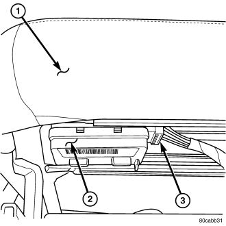
1. Working under the front seat cushion (1), remove the heated seat module (2) from its mounting bracket by gently prying the module off of the two mounting pushpins.
2. Disconnect the seat wire harness connector (3) from the connector receptacle on the side of the heated seat module (2).
3. Remove the heated seat module from the vehicle.
INSTALLATION
1. Connect the seat wire harness connector (3) to the connector receptacle on the side of the heated seat module (2).
2. Install the heated seat module (2) on its mounting bracket under the front seat (1).
3. Verify heated seat system operation.