BALANCE SHAFT
DESCRIPTION
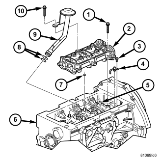
The 2.8L Common Rail Diesel engine is equipped with two gear driven nodular cast iron balance shafts in a cast aluminum carrier. The balance shaft assembly (2) is gear driven by the crankshaft and used to counteract engine vibration.
OPERATION
The balance shaft assembly includes four balancers on two shafts. The balance shafts are connected by helical gears, and the assembly is timed with the engine. The dual-counter rotating shafts rotate at twice the engine speed and decrease second order vertical shaking forces caused by component movement. Balance shaft oiling is provided through oil passages in the crankshaft carriers.
REMOVAL
1. Disconnect negative battery cable.
2. Raise vehicle on hoist.
3. Remove oil pan (Refer to 9 - ENGINE/LUBRICATION/OIL PAN - REMOVAL) .
4. Remove oil pump pickup tube (Refer to 9 - ENGINE/LUBRICATION/OIL PUMP - REMOVAL) .
5. Remove balance shaft assembly (2) and discard O-rings (7) on the central carrier pins.
INSTALLATION
CAUTION: Install new O-rings on the carrier pins and oil pick up tube before assembly.
NOTE: Before installation of the balance shaft assembly, the # 1 cylinder must be brought to TDC, or the 12 O'clock position. There is a line on the front of the crankshaft hub, next to the front crankshaft bolt, that may assist the alignment .
1. Remove the vibration damper and roll engine over by hand until the witness line on the front of the crankshaft hub is at the 12 O'clock, or TDC position. Once the # 1 cylinder is brought to TDC, the balance shaft assembly can be installed.
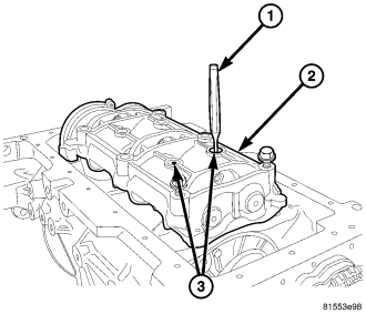
CAUTION: CARE MUST BE TAKEN DURING THE INSTALLATION OF THE DRIFT OR PUNCH. THE BACK SIDE OF THE COUNTER WEIGHTS ON THE BALANCE SHAFTS MUST BE IN THE UP POSITION BEFORE INSERTING THE TOOL INTO THE HOUSING.
2. With balance shaft assembly on work bench. Insert a drift or a punch (11) into balance shaft assembly (2) alignment hole (3). This will ensure proper balance shaft to crankshaft timing after assembly .
3. Install the new crankshaft carrier pin O-rings, balance shaft assembly and retaining bolts . Torque bolts to 32.4N·m (24 ft. lbs.), and remove the punch from the alignment hole.
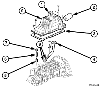
4. Install oil pump pickup tube with new seals (Refer to 9 - ENGINE/LUBRICATION/OIL PUMP - INSTALLATION).
5. Install oil pan (Refer to 9 - ENGINE/LUBRICATION/OIL PAN - INSTALLATION) .
6. Refill engine oil to proper level.
7. Connect negative battery cable.