CAMSHAFT(S)
DESCRIPTION
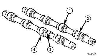
The camshafts (1) and (4) are made of gray cast iron with eight machined lobes and four bearing journals. Each camshaft has an alignment hole (2) and (3) toward the front of the camshaft that is used during base engine timing procedures (Refer to 9 - ENGINE/VALVE TIMING - STANDARD PROCEDURE).
OPERATION
When the camshaft rotates the lobes actuate the hydraulic lifters and rocker arms, forcing downward on the rocker arms which opens the valves.
REMOVAL - CAMSHAFTS
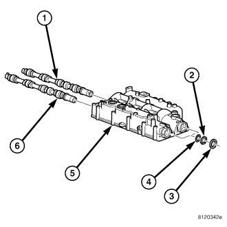
1. Disconnect negative battery cable.
2. Remove engine cover and bracket (Refer to 9 - ENGINE - REMOVAL).
3. Drain cooling system (Refer to 7 - COOLING/ENGINE/COOLANT - STANDARD PROCEDURE).
4. Remove cooling fan and fan drive viscous clutch assembly (Refer to 7 - COOLING/ENGINE/FAN DRIVE VISCOUS CLUTCH - REMOVAL).
5. Remove accessory drive belt (Refer to 7 - COOLING/ACCESSORY DRIVE/DRIVE BELTS - REMOVAL).
6. Remove cooling fan support (Refer to 7 - COOLING/ENGINE/RADIATOR FAN - REMOVAL).
7. Rotate the engine to 90 degrees ATDC and install special tool VM.1089. (Refer to 9 - ENGINE/VALVE TIMING - STANDARD PROCEDURE).
8. Remove vibration damper (Refer to 9 - ENGINE/ENGINE BLOCK/VIBRATION DAMPER - REMOVAL).
9. Remove generator (Refer to 8 - ELECTRICAL/CHARGING/GENERATOR - REMOVAL).
CAUTION: Before removing the cylinder head cover/intake manifold (5) or timing belt the engine must rotated to the 90° ATDC, or the 3 O'clock position and special tool VM.1089 installed in the 90 degree ATDC alignment hole. Failure to do so could result in valve and/or piston damage during reassembly. (Refer to 9 - ENGINE/VALVE TIMING - STANDARD PROCEDURE)
10. Remove timing belt outer cover (Refer to 9 - ENGINE/VALVE TIMING/TIMING BELT / CHAIN COVER(S) - REMOVAL).
11. Remove timing belt (Refer to 9 - ENGINE/VALVE TIMING/TIMING BELT/CHAIN AND SPROCKETS - REMOVAL).
12. Remove timing belt inner cover (Refer to 9 - ENGINE/VALVE TIMING/TIMING BELT / CHAIN COVER(S) - REMOVAL).
13. Remove cylinder head cover/intake manifold (Refer to 9 - ENGINE/CYLINDER HEAD/CYLINDER HEAD COVER(S) - REMOVAL).
14. With cylinder head cover/intake manifold on work bench, remove plugs at rear of cylinder head cover/intake manifold.
15. Remove camshaft oil seals .
16. Remove snap ring (2) and thrust washer (4) from camshaft.
17. Slide camshaft through access hole at rear of cylinder head cover/intake manifold (5).
INSTALLATION - CAMSHAFTS
1. Lubricate camshafts with Mopar® Engine Oil Supplement, or equivalent.
2. Carefully install camshafts into access holes in rear of cylinder head cover/intake manifold.
3. Install thrust washer, snap ring, and camshaft oil seal .
CHECKING CAMSHAFT ENDPLAY
1. After camshafts are properly installed in cylinder head cover check end play of camshafts with a dial indicator. The end play should be between 0.10 mm - 0.55 mm .
NOTE: If the camshaft endplay is not within specification, measure thickness of the camshaft spacer. Camshaft spacer thickness should be 2.8 ± .02mm.
4. Measure the camshaft end play with a dial indicator. The end play should be between 0.10 mm-0.55 mm.
5. Install access hole plugs and gaskets at rear of cylinder head cover/intake manifold. Torque plugs to 80N·m.(59 ft. lbs.).
6. Install cylinder head cover/intake manifold on engine block (Refer to 9 - ENGINE/CYLINDER HEAD/CYLINDER HEAD COVER(S) - INSTALLATION).
7. Align the camshafts and install camshaft alignment pins, VM1052 and VM1053 into the camshaft cover.
8. Install timing belt inner cover (Refer to 9 - ENGINE/VALVE TIMING/TIMING BELT / CHAIN COVER(S) - INSTALLATION).
NOTE: Crankshaft must be rotated to the 90 degree ATDC, or the 3 O'clock position (Refer to 9 - ENGINE/VALVE TIMING - STANDARD PROCEDURE).
9. Install timing belt (Refer to 9 - ENGINE/VALVE TIMING/TIMING BELT/CHAIN AND SPROCKETS - INSTALLATION).
10. Install timing belt outer cover (Refer to 9 - ENGINE/VALVE TIMING/TIMING BELT / CHAIN COVER(S) - INSTALLATION).
11. Install generator (Refer to 8 - ELECTRICAL/CHARGING/GENERATOR - INSTALLATION).
12. Install vibration damper.
13. Install cooling fan support (Refer to 7 - COOLING/ENGINE/RADIATOR FAN - INSTALLATION).
14. Install accessory drive belt (Refer to 7 - COOLING/ACCESSORY DRIVE/DRIVE BELTS - INSTALLATION).
15. Install cooling fan and fan drive viscous clutch assembly (Refer to 7 - COOLING/ENGINE/FAN DRIVE VISCOUS CLUTCH - INSTALLATION).
16. Refill cooling system (Refer to 7 - COOLING/ENGINE/COOLANT - STANDARD PROCEDURE).
17. Connect negative battery cable.