HEAD-CYLINDER
DESCRIPTION
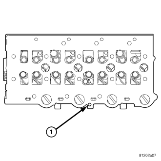
The 2.8L aluminum, overhead valve cylinder head (1) has different dimensions for the intake air and a bias relief port. The cylinder head itself is not resurfacable. The cylinder head uses a selectable Multi-layered Steel gasket that is available in three sizes.
REMOVAL
1. Disconnect negative battery cable.
2. Remove engine cover and bracket (Refer to 9 - ENGINE COVER - REMOVAL).
3. Drain cooling system (Refer to 7 - COOLING/ENGINE/COOLANT - STANDARD PROCEDURE).
4. Remove radiator core support.
5. Remove cooling fan and fan drive viscous clutch assembly (Refer to 7 - COOLING/ENGINE/FAN DRIVE VISCOUS CLUTCH - REMOVAL).
6. Remove accessory drive belt (Refer to 7 - COOLING/ACCESSORY DRIVE/DRIVE BELTS - REMOVAL).
7. Remove accessory drive belt tensioner and both idler pulleys, Idler pulley bolts are L.H. thread. (Refer to 7 - COOLING/ACCESSORY DRIVE/BELT TENSIONERS - REMOVAL).
8. Remove power steering pump pulley.
9. Remove front engine lift bracket.
10. Remove cooling fan support (Refer to 7 - COOLING/ENGINE/RADIATOR FAN - REMOVAL).
11. Remove generator and support bracketing (Refer to 8 - ELECTRICAL/CHARGING/GENERATOR - REMOVAL).
12. Remove viscous heater.
13. Remove vibration damper.
14. Remove throttle cable assembly and set aside.
15. Disconnect main engine wiring harness connectors from right inner wheel housing.
16. Disconnect main engine wiring harness ancillary components and set harness aside.
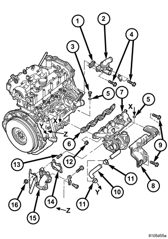
17. Remove air cleaner housing .
18. Disconnect EGR cooler assembly water inlet pipe.
19. Remove EGR cooler from exhaust manifold (2.8L) Disconnect coolant pipe (2.5L). (Refer to 25 - EMISSIONS CONTROL/EXHAUST GAS RECIRCULATION/VALVE COOLER - REMOVAL).
20. Remove exhaust manifold heat shield (8).
21. Remove turbocharger heat shield retaining bolt and position shield aside.
22. Remove turbocharger oil feed line from turbocharger.
23. Raise and support vehicle.
24. Disconnect exhaust stabilizer bracket at lower exhaust manifold.
25. Disconnect exhaust system bracket at transmission crossmember.
26. Lower the vehicle and remove the exhaust manifold retaining nuts.
27. Slide the exhaust manifold and turbocharger off of exhaust manifold studs.
28. Remove coolant hoses at thermostat housing.
29. Disconnect fuel return hose from fuel injectors and set aside (Refer to 14 - FUEL SYSTEM/FUEL INJECTION/FUEL INJECTOR - REMOVAL).
30. Remove fuel injector pressure lines (Refer to 14 - FUEL SYSTEM/FUEL INJECTION/FUEL INJECTOR - REMOVAL).
31. Disconnect fuel pump high pressure line at fuel rail (Refer to 14 - FUEL SYSTEM/FUEL INJECTION/FUEL INJECTOR - REMOVAL).
32. Disconnect oil dip stick tube from intake manifold.
33. Disconnect brake booster line bracket from intake manifold and set aside.
34. Remove fuel injectors (Refer to 14 - FUEL SYSTEM/FUEL INJECTION/FUEL INJECTOR - REMOVAL).
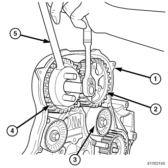
CAUTION: Before removing the cylinder head cover/intake manifold or timing belt the engine must put at 90° after TDC. Failure to do so could result in valve and/or piston damage during reassembly. (Refer to 9 - ENGINE/VALVE TIMING - STANDARD PROCEDURE)
35. Remove timing belt outer cover (Refer to 9 - ENGINE/VALVE TIMING/TIMING BELT / CHAIN COVER(S) - REMOVAL).
36. Remove timing belt (Refer to 9 - ENGINE/VALVE TIMING/TIMING BELT/CHAIN AND SPROCKETS - REMOVAL).
37. Using VM.1055 (5), remove both camshaft gears.
38. Remove timing belt inner cover (Refer to 9 - ENGINE/VALVE TIMING/TIMING BELT / CHAIN COVER(S) - REMOVAL).
39. Remove cylinder head cover/intake manifold (Refer to 9 - ENGINE/CYLINDER HEAD/CYLINDER HEAD COVER(S) - REMOVAL).
40. Remove rocker arm and lifter assemblies from cylinder head. Be sure to keep in same order as removed.
41. Remove cylinder head cover/intake manifold gasket from cylinder head.
42. Disconnect glow plug and engine coolant temperature electrical connectors.
43. Remove turbocharger outlet to charge air cooler hose.
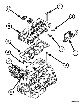
44. Remove cylinder head bolts (1).
45. Remove cylinder head assembly from engine block (9).
CLEANING
Thoroughly clean the engine cylinder head and cylinder block mating surfaces. Clean the intake and exhaust manifold and engine cylinder head mating surfaces. Remove all gasket material and carbon.
Check to ensure that no coolant or foreign material has fallen into the tappet bore area.
Remove the carbon deposits from the combustion chambers and top of the pistons.
INSPECTION
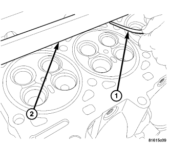
CAUTION: The cylinder head surface and straight edge must be absolutely clean before the flatness measurement is taken. DO NOT check flatness across the combustion chamber area or on the marks left by the gasket stopper.
Use a cleaned straight edge (2) and feeler (1) gauge to check the flatness. Lie the straight edge (2) parallel across the cooling ports, Measure before each combustion chamber toward the outer edge of the cylinder head, above and below each combustion chamber, between each combustion chamber, top and bottom, on the cylinder head and block mating surfaces. The maximum allowed warpage is 0.1mm (0.004 in.).
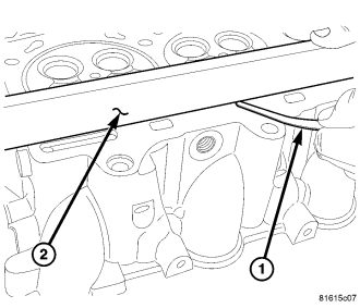
The minimum cylinder head thickness is 89.95mm (3.541 in.).
INSTALLATION
CAUTION: Piston protrusion must be measured to determine cylinder head gasket thickness if one or more cylinder liners have been replaced (Refer to 9 - ENGINE/CYLINDER HEAD - STANDARD PROCEDURE).
NOTE: If cylinder liner(s) have not been removed, the same thickness head gasket that was removed can be used.
1. Clean and inspect gasket mating surfaces.
2. Position correct head gasket on engine block.
3. Place cylinder head on engine block.
CAUTION: New cylinder head bolts must be used. Do Not lubricate new cylinder head bolts. They already are coated with an anti scuff treatment.
4. Tighten cylinder head bolts following procedure below.
Cylinder Head Bolt Torquing Procedure
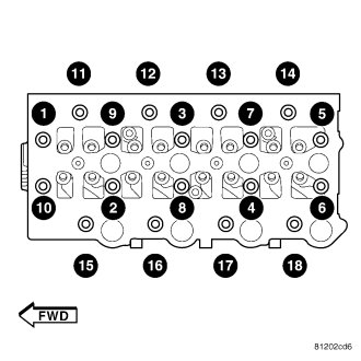
1. Tighten all cylinder head bolts to 30 N·m (22 ft. lbs.) starting from the center bolts, following the cylinder head scheme and the following sequence: 3-2-1-10-9-8-7-6-5-4-11-12-13-14-15-16-17-18.
2. Without loosening any bolts, starting from the center bolts, tighten each bolt an additional 75° in the following sequence: 10-9-8-7-6-5-4-3-2-1.
3. Tighten the lateral cylinder head bolts an additional 50° in the following sequence: 11-12-13-14-15-16-17-18.
4. Finally tighten all bolts an additional 75° in the following sequence: 10-9-8-7-6-5-4-3-2-1-11-12-13-14-15-16-17-18.
5. Slide exhaust manifold and turbocharger on exhaust manifold studs.
6. Install exhaust manifold retaining nuts (12). Tighten the nuts to 36 N·m (26.5 ft. lbs.) in a cross sequence beginning in the middle and working outward, then perform the tightening sequence to the exhaust manifold nuts again.
7. Install exhaust manifold heat shield (8). Torque bolts to 24.5 N·m (18 ft. lbs.).
8. Install turbocharger outlet to charge air cooler pipe.
9. Install upper radiator hose.
10. Connect glow plug and coolant temperature sensor electrical connectors.
11. Install new cylinder head cover/intake manifold gasket.
12. Install rocker arm and lifter assemblies.Be sure to put rocker arm and lifter assemblies in same location as removed.
13. Install cylinder head cover/intake manifold (Refer to 9 - ENGINE/CYLINDER HEAD/CYLINDER HEAD COVER(S) - INSTALLATION).
14. Install timing belt inner cover (Refer to 9 - ENGINE/VALVE TIMING/TIMING BELT / CHAIN COVER(S) - INSTALLATION).
15. Using VM.1055 (5), install both camshaft gears and tighten bolts finger tight.
16. Install timing belt (Refer to 9 - ENGINE/VALVE TIMING/TIMING BELT/CHAIN AND SPROCKETS - INSTALLATION).
17. Using VM.1055 (5), torque cam gear retaining bolts to 108 N·m (80 ft. lbs.).
18. Install timing belt outer cover (Refer to 9 - ENGINE/VALVE TIMING/TIMING BELT / CHAIN COVER(S) - INSTALLATION).
19. Remove crankshaft and both camshaft locking pins at this time (Refer to 9 - ENGINE/VALVE TIMING - STANDARD PROCEDURE).
20. Install fuel injectors (Refer to 14 - FUEL SYSTEM/FUEL INJECTION/FUEL INJECTOR - INSTALLATION).
21. Install brake booster line bracket to intake manifold.
22. Install oil dip stick tube to intake manifold.
23. Connect fuel pump high pressure line to fuel rail.
24. Install fuel injector pressure lines.
25. Connect fuel return hose to fuel injectors.
26. Connect engine coolant hoses to thermostat housing.
27. Raise vehicle.
28. Reconnect exhaust system bracket at transmission crossmember.
29. Connect exhaust stabilizer bracket to lower exhaust manifold .
30. Install turbocharger oil feed line to turbocharger.
31. Lower vehicle.
32. Install turbocharger heat shield.
33. Install exhaust manifold heat shield.
34. Install EGR cooler assembly and connect engine coolant hoses.
35. Install air cleaner housing.
36. Install main engine wiring harness and connect all ancillary electrical components.
37. Install throttle cable assembly.
38. Install viscous heater.
39. Install vibration damper.
40. Install generator (Refer to 8 - ELECTRICAL/CHARGING/GENERATOR - INSTALLATION).
41. Install cooling fan support (Refer to 7 - COOLING/ENGINE/RADIATOR FAN - INSTALLATION) .
42. Install front engine lift bracket.
43. Install power steering pump pulley.
44. Install accessory drive belt tensioner and both idler pulleys. Idler pulley retaining bolts are L. H. Thread.
45. Install accessory drive belt (Refer to 7 - COOLING/ACCESSORY DRIVE/DRIVE BELTS - INSTALLATION).
46. Install cooling fan and fan drive viscous clutch assembly (Refer to 7 - COOLING/ENGINE/FAN DRIVE VISCOUS CLUTCH - INSTALLATION) .
47. Install upper radiator core support.
48. Refill cooling system (Refer to 7 - COOLING/ENGINE/COOLANT - STANDARD PROCEDURE).
49. Install engine cover and bracket (Refer to 9 - ENGINE COVER - INSTALLATION) .
50. Connect negative battery cable.
51. Start engine and inspect for leaks (Refer to 14 - FUEL SYSTEM - WARNING).