LINERS-CYLINDER
DESCRIPTION
Each cylinder wall liner used on this engine is of the wet design. Coolant is in direct contact with the liner. Three O-rings are used to seal the liner to the engine block. The top O-rings (black) are water seals and the lower (brown) seal is an oil seal. The applicable metal shim is used for cylinder liner protrusion. If the liner is to be reused, match mark the liner and block. Anytime that the liners are removed, replace the O-rings and the shim. If one or more liners have been replaced the liner protrusion must be measured to determine the proper head gasket selection. If the liners are not removed, used the same thickness head gasket that was removed.
REMOVAL
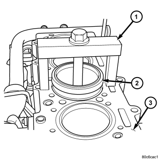
CAUTION: To prevent damage to the oil jets, remove the oil jets before removing the pistons or liners.
1. Remove engine from vehicle.
2. With engine completely disassembled, use special tool VM.1001 (1) to remove cylinder liner (2).
3. Tighten bolt on VM.1001 (1) to remove cylinder liner (2) from engine block (3).
4. Remove shim(s) from cylinder liner (2) or cylinder block recess. Keep shim(s) with each cylinder liner (2) until cylinder liner (2) protrusion measurement.
INSPECTION
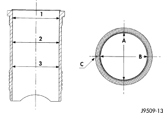
The cylinder walls should be checked for out-of-round and taper with a dial bore gauge. The cylinder bore out-of-round is 0.100 mm (.0039 in.) maximum and cylinder bore taper is 0.100 mm (.0039 in.) maximum. If the cylinder walls are badly scuffed or scored, new liners should be installed and honed, and new pistons and rings fitted.
Measure the cylinder bore at three levels in directions A and B. Top measurement should be 10 mm (3/8 in.) down and bottom measurement should be 10 mm (3/8 in.) up from the bottom bore.
INSTALLATION
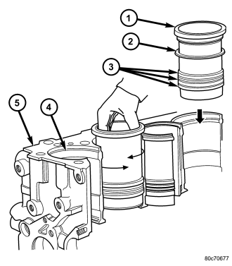
CAUTION: Cleanliness can not be over emphasized enough when cleaning the cylinder liner (1) to engine block (5) mating surfaces. Failure to do so will result in the wrong protrusion reading. Only one shim (2) per sleeve fitting. DO NOT stack or re-use shims (2).
NOTE: When installing cylinder liners (1) for protrusion measurement, remove all O-rings (3) and discard original shim (2).
1. Carefully clean cylinder liner (1) and engine block (5), and degrease the engine block deck where it comes into contact with the cylinder liners (1). Install the cylinder liners in the engine block (5) as shown, rotating them back and forth by 45° in order to guarantee correct positioning.
NOTE: All Measurements Must Be Taken On the High Pressure Pump Side.
2. Measure the cylinder liner (1) recess relative to block deck with dial indicator VM.1013 mounted on a special tool VM.1010 A. . Zero dial gauge on block deck.
NOTE: The cylinder liner (1) reading will actually be a negative number.
3. Move dial gauge to cylinder liner (1) edge record reading on dial gauge. The reading should be negative.
4. Remove cylinder liner (1) and special tools.
5. Then select the correct shim (2) thickness to give proper protrusion (0.00 - 0.05 mm).
NOTE: The O-rings (3) are used toward the bottom of the cylinder liner (1). Each cylinder liner (1) has three O-rings (3) that prevent coolant and engine oil from mixing. The brown (bottom) O-ring (3) is an oil seal and the two black (top) O-rings (3) are water seals.
6. Fit the proper shim (2), and the O-rings (3), onto the cylinder liner (1).
7. Lubricate the lower cylinder liner (1) location in the engine block (5).
CAUTION: When installing special tool VM.1076, make sure the tool does not rotate when tightening and damage the cylinder liner (1). DO NOT rotate the engine with out special tool VM.1076 in position.
8. Fit the cylinder liners in the crankcase making sure that the shim (2) is positioned correctly in the seat. Lock the cylinder liners (1) in position using special tool (VM.1076) and bolts tightened to 50 N·m (37 ft.lbs.).
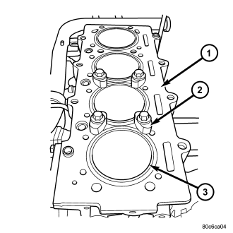
NOTE: After measuring cylinder liner (1) protrusion again, piston protrusion must be measured to prevent the wrong cylinder head gasket selection.
9. Measure cylinder liner (1) protrusion again. It should be 0.00 - 0.05 mm.
10. Reassemble engine.
11. Install engine in vehicle.