PUMP-INTERNAL VACUUM
DESCRIPTION
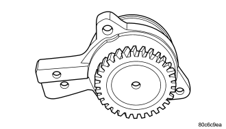
The diesel engine uses a internal vacuum pump. This vacuum pump is mounted in the front of the engine block under the engine front cover. The vacuum pump is driven by a sprocket on the crankshaft.
REMOVAL
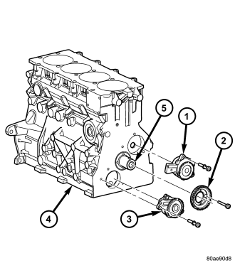
1. Disconnect negative battery cable.
2. Remove cooling fan and fan drive viscous clutch assembly (Refer to 7 - COOLING/ENGINE/FAN DRIVE VISCOUS CLUTCH - REMOVAL).
3. Remove accessory drive belt (Refer to 7 - COOLING/ACCESSORY DRIVE/DRIVE BELTS - REMOVAL).
4. Remove cooling fan support (Refer to 7 - COOLING/ENGINE/RADIATOR FAN - REMOVAL).
5. Remove vibration damper/crankshaft pulley (Refer to 9 - ENGINE/ENGINE BLOCK/VIBRATION DAMPER - REMOVAL).
6. Rotate the engine to 90 degrees ATDC and install alignment pin VM.1089 (Refer to 9 - ENGINE/VALVE TIMING - STANDARD PROCEDURE).
7. Remove outer timing belt cover (Refer to 9 - ENGINE/VALVE TIMING/TIMING BELT / CHAIN COVER(S) - REMOVAL).
CAUTION: Before removing the cylinder head cover/intake manifold or timing belt the engine must rotated to the 90° ATDC and special tool VM.1089 alignment pin installed. Failure to do so could result in valve and/or piston damage during reassembly. (Refer to 9 - ENGINE/VALVE TIMING - STANDARD PROCEDURE)
8. Remove timing belt (Refer to 9 - ENGINE/VALVE TIMING/TIMING BELT/CHAIN AND SPROCKETS - REMOVAL).
9. Remove timing belt inner cover (Refer to 9 - ENGINE/VALVE TIMING/TIMING BELT / CHAIN COVER(S) - REMOVAL).
NOTE: Crankshaft hub has LHD thread.
10. Remove crankshaft hub.
11. Remove front engine cover (Refer to 9 - ENGINE/ENGINE BLOCK/ENGINE COVER - REMOVAL).
12. Remove crankshaft sprocket.
13. Remove vacuum pump (1).
INSTALLATION
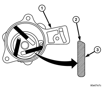
NOTE: Verify the 3 blades on the vacuum pump are in place and correctly assembled. The tapered edge should be on the outer side. Make sure the pump rotates before installation.
1. Lubricate vacuum pump components and install in engine block. Torque bolts to 10.8N·m.
2. Install crankshaft sprocket. Torque bolts to 10.8N·m.
3. Install front engine cover (Refer to 9 - ENGINE/ENGINE BLOCK/ENGINE COVER - INSTALLATION).
4. Install front crankshaft hub. Torque bolt to 304N·m.
5. Install timing belt inner cover (Refer to 9 - ENGINE/VALVE TIMING/TIMING BELT / CHAIN COVER(S) - INSTALLATION).
6. Install timing belt (Refer to 9 - ENGINE/VALVE TIMING/TIMING BELT/CHAIN AND SPROCKETS - INSTALLATION).
7. Install timing belt outer cover (Refer to 9 - ENGINE/VALVE TIMING/TIMING BELT / CHAIN COVER(S) - INSTALLATION).
8. Remove special tool VM.1080 from the engine block 90 degree ATDC alignment hole.
9. Install vibration damper/crankshaft pulley (Refer to 9 - ENGINE/ENGINE BLOCK/VIBRATION DAMPER - INSTALLATION).
10. Install cooling fan support (Refer to 7 - COOLING/ENGINE/RADIATOR FAN - INSTALLATION).
11. Install accessory drive belt (Refer to 7 - COOLING/ACCESSORY DRIVE/DRIVE BELTS - INSTALLATION).
12. Install cooling fan and fan drive viscous clutch assembly (Refer to 7 - COOLING/ENGINE/FAN DRIVE VISCOUS CLUTCH - INSTALLATION).
13. Connect negative battery cable.