TIMING BELT/CHAIN AND SPROCKET(S)
REMOVAL
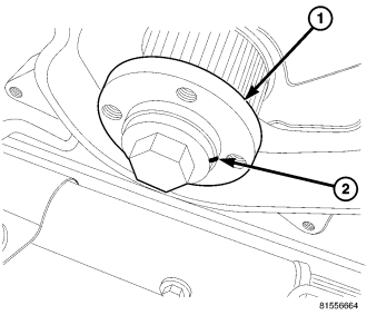
CAUTION: Before removing the timing belt, the engine must be placed at 90° atdc and alignment pin vm.1089 installed. Failure to do so may result in valve and/or piston damage during assembly. (Refer to 9 - ENGINE/VALVE TIMING - STANDARD PROCEDURE)
1. Disconnect negative battery cable.
2. Remove engine cover (Refer to 9 - ENGINE COVER - REMOVAL) .
3. Remove cooling fan and fan drive viscous clutch assembly (Refer to 7 - COOLING/ENGINE/FAN DRIVE VISCOUS CLUTCH - REMOVAL) .
4. Remove accessory drive belt (Refer to 7 - COOLING/ACCESSORY DRIVE/DRIVE BELTS - REMOVAL) .
5. Remove cooling fan support (Refer to 7 - COOLING/ENGINE/RADIATOR FAN - REMOVAL) .
6. Remove vibration damper (Refer to 9 - ENGINE/ENGINE BLOCK/VIBRATION DAMPER - REMOVAL) .
7. Bring piston #1 to TDC, turn crankshaft until the witness line on the crankshaft hub is at the 12 o'clock position.
8. Looking at the engine from the belt side, rotate the crankshaft 90° clockwise so the witness mark is now at the 3 O'clock position and install special tool VM.1089 (Refer to 9 - ENGINE/VALVE TIMING - STANDARD PROCEDURE).
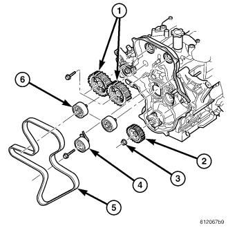
9. Remove the alternator.
10. Remove the intake and exhaust camshaft plugs from the camshaft cover, to introduce the camshaft timing pins VM.1052 Intake, and VM.1053 Exhaust (if the engine is timed correctly, the pins can be installed flush with the intake manifold/cylinder head cover). (Refer to 9 - ENGINE/VALVE TIMING - STANDARD PROCEDURE).
11. Remove timing belt outer cover (Refer to 9 - ENGINE/VALVE TIMING/TIMING BELT / CHAIN COVER(S) - REMOVAL) .
12. Loosen timing belt tensioner and remove timing belt.
13. Remove the intake and exhaust camshaft alignment pins, VM.1052 Intake, and VM.1053 Exhaust.
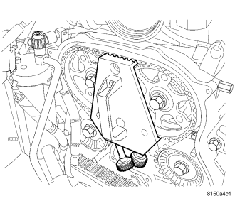
14. Loosen camshaft gears using special tool VM 1085 to retain the gears when loosening the bolts.
15. Remove special tool VM 1085.
INSTALLATION
NOTE: There are marks on both camshaft gears. These ARE NOT alignment marks and should be disregarded.
1. With both camshaft alignment pins still installed and the crankshaft aligned at 90° A.T.D.C. with VM.1089 alignment pin installed (Refer to 9 - ENGINE/VALVE TIMING - STANDARD PROCEDURE), verify that the camshaft gears are loose.
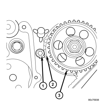
2. Align the timing mark on the high pressure injection pump gear with the timing mark on the inner cover
NOTE: DO NOT remove the timing belt from the package until it's ready to be installed. DO NOT expose timing belt to oil, grease or water contamination. DO NOT crimp belt at a sharp angle. DO NOT clean belt, pulleys or tensioner with solvent. Check that pulleys and bearings are not seized or damage before installing belt.
3. Install timing belt on crankshaft hub.
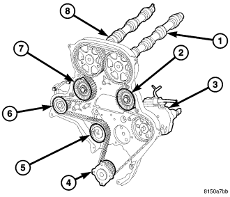
4. Route the belt around high pressure injection pump, idler pulley, intake camshaft gear, exhaust camshaft gear, idler pulley, and water pump gear .
5. Adjust the timing belt tensioner (turn it clockwise) using special tool VM.9660, lining up the center notch with the aluminum cover dowel pin. Tighten the retaining bolt to 28N·m.( 20 ft. lbs.). (Refer to 9 - ENGINE/VALVE TIMING/TMNG BELT/CHAIN TENSIONER&PULLEY - ADJUSTMENTS).
6. Install special tool VM.1085 between camshaft gears and tighten thumb screws to engage and retain the camshaft gears .
7. Tighten the camshaft gear bolts to 108 N·m (80 ft.lbs.) while holding the gears with special tool VM 1085.
8. Remove VM.1085, camshaft gear locking tool and VM.1089 alignment pin.
9. Remove intake and exhaust camshaft alignment pins (VM.1052 and VM.1053). .
WARNING: If intake manifold/cylinder head cover was removed wait 30 minutes before rotating crankshaft.
10. Rotate the engine clockwise 2 revolutions (looking at engine from the belt side).
11. With the crankshaft hub witness mark aligned to 90 degrees ATDC, or the three O'clock positionand alignment pin VM.1089 installed, check that the intake and exhaust camshaft alignment pins (VM 1052 and VM 1053) can be installed into the camshaft alignment access holes.
WARNING: If the camshaft alignment pins can not be installed at this time, repeat the procedure from the beginning.
12. Install timing belt outer cover (Refer to 9 - ENGINE/VALVE TIMING/TIMING BELT / CHAIN COVER(S) - INSTALLATION) .
13. Install the camshaft access plugs.
14. Install vibration damper (Refer to 9 - ENGINE/ENGINE BLOCK/VIBRATION DAMPER - INSTALLATION) .
15. Install the alternator.
16. Install cooling fan support (Refer to 7 - COOLING/ENGINE/RADIATOR FAN - INSTALLATION) .
17. Install accessory drive belt (Refer to 7 - COOLING/ACCESSORY DRIVE/DRIVE BELTS - INSTALLATION) .
18. Install cooling fan and fan drive viscous clutch assembly (Refer to 7 - COOLING/ENGINE/FAN DRIVE VISCOUS CLUTCH - INSTALLATION) .
19. Install engine cover (Refer to 9 - ENGINE COVER - INSTALLATION) .
20. Remove special tool VM.1089.
21. Connect negative battery cable.