VALVE TIMING
STANDARD PROCEDURE - LOCKING ENGINE 90 DEGREES AFTER TDC
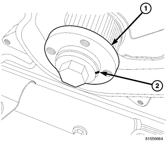
1. Disconnect negative battery cable.
2. Remove the vibration damper (Refer to 9 - ENGINE/ENGINE BLOCK/VIBRATION DAMPER - REMOVAL).
NOTE: Rotate the engine by the front crankshaft bolt until the witness mark next to the bolt in the front crankshaft hub reaches the 12 o'clock position, or TDC. Rotate the engine another 1/4 turn to the right, rotating the witness mark to the three o'clock position, or 90 degrees ATDC.
3. Rotate engine by hand until the witness mark (2) in the front crankshaft hub (1) reaches the 3 O'clock position.
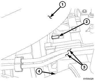
4. Raise and support the vehicle.
5. Remove the splash shield.
CAUTION: A properly installed alignment pin will have no threads showing once threaded into the access hole. The engine block, flywheel, and/or flex plate, have an alignment hole to assist in properly aligning the crankshaft before service. Failure to properly align the crankshaft, or forcing the VM.1089 alignment pin, may result in improper valve timing and engine damage. DO NOT rotate the engine counterclockwise.
CAUTION:
NOTE: It may be necessary to rotate the engine to 90 degrees ATDC several times before proper alignment occurs. This alignment is precise and exact to prevent engine damage while servicing the timing components.
6. Insert the VM.1089 (2) alignment pin into the 90 degree ATDC alignment access hole. Tighten pin by hand until no threads on the tool are visible.
7. Lower the vehicle.
8. Remove engine cover (Refer to 9 - ENGINE COVER - REMOVAL) .
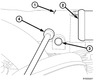
9. Remove the exhaust camshaft access plug in cylinder head cover/intake manifold.
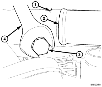
CAUTION: DO NOT force the pin into the access hole. VM.1053 should screw in by hand and mount flush with the intake manifold/cylinder head cover. If the tool can not be inserted, remove the tool, remove the VM 1089 90 degree A.T.D.C. pin, and rotate the engine another 180 degrees to the 3 O'clock position and try again.
10. Insert VM.1053 (3) to lock exhaust camshaft in position.
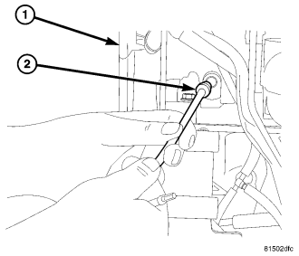
11. Remove the left plug in cylinder head cover/intake manifold .
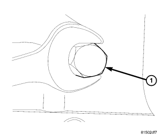
12. Insert VM.1052 (1) to lock intake camshaft in position .
13. At this point the timing belt can be removed for service.
14. After engine service is completed, remove special tool VM 1089 from the 90 degrees A.T.D.C. access hole and remove both camshaft locking pins from cylinder head cover/intake manifold.
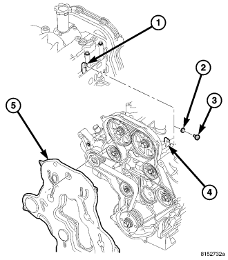
15. Install both camshaft access plugs (3). Tighten the access plugs to 10.8 N.m (95 in. lbs.).
16. Remove 90 degree A.T.D.C. alignment pin.
17. Install engine cover (Refer to 9 - ENGINE COVER - INSTALLATION) .
18. Connect negative battery cable.
19.