ROCKER ARM - VALVE
DESCRIPTION
The rocker arms are steel stampings with an integral roller bearing. The rocker arms incorporate a 0.5 mm oil jet hole in the lash adjuster socket for roller and camshaft lubrication.
REMOVAL
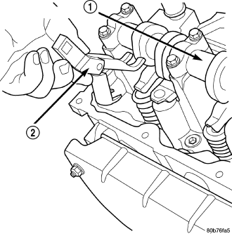
NOTE: Disconnect the battery negative cable to prevent accidental starter engagement.
1. Remove the cylinder head cover (Refer to 9 - ENGINE/CYLINDER HEAD/CYLINDER HEAD COVER(S) - REMOVAL).
2. For rocker arm removal on cylinder No. 4, Rotate the crankshaft until cylinder No. 1 is at BDC intake stroke.
3. For rocker arm removal on cylinder No. 1, Rotate the crankshaft until cylinder No. 1 is at BDC combustion stroke.
4. For rocker arm removal on cylinders No. 3 and No. 5, Rotate the crankshaft until cylinder No. 1 is at TDC exhaust stroke.
5. For rocker arm removal on cylinders No. 2 and No. 6, Rotate the crankshaft until cylinder No. 1 is at TDC ignition stroke.
6. Using special tool 8516 Rocker Arm Remover (2) , press downward on the valve spring, remove rocker arm.
INSTALLATION
CAUTION: Make sure the rocker arms are installed with the concave pocket over the lash adjusters. Failure to do so may cause severe damage to the rocker arms and/or lash adjusters.
NOTE: Coat the rocker arms with clean engine oil prior to installation.
1. For rocker arm installation on cylinders No. 4, Rotate the crankshaft until cylinder No. 1 is at BDC intake stroke.
2. For rocker arm installation on cylinder No. 1, Rotate the crankshaft until cylinder No. 1 is at BDC combustion stroke.
3. For rocker arm installation on cylinders No. 3 and No. 5, Rotate the crankshaft until cylinder No. 1 is at TDC exhaust stroke.
4. For rocker arm installation on cylinders No. 2 and No. 6, Rotate the crankshaft until cylinder No. 1 is at TDC ignition stroke.
5. Using special tool 8516 (2) press downward on the valve spring, install rocker arm.
6. Install the cylinder head cover (Refer to 9 - ENGINE/CYLINDER HEAD/CYLINDER HEAD COVER(S) - INSTALLATION).