*CHECKING THE ACCELERATOR PEDAL POSITION SENSOR CALIBRATION
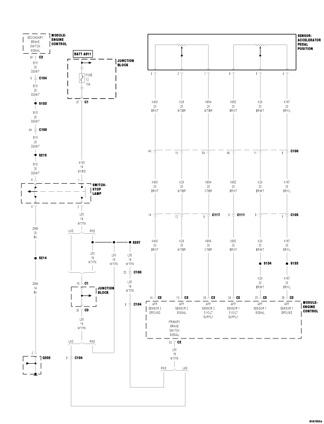
For a complete wiring diagram Refer to Section 8W
Theory of Operation
The Accelerator Pedal Position Sensor (APP) is a device that contains 2 separate potentiometer type sensors. Each sensor has its own 5-volt supply circuit, sensor ground circuit and signal circuit.
The APP Sensor 2 signal should always be approximately 1/2 the voltage of the APP Sensor 1 signal.
| Possible Causes |
| APP SENSOR OPERATION |
| APP SENSOR CIRCUIT 1 HIGH RESISTANCE |
| APP SENSOR CIRCUIT 2 HIGH RESISTANCE |
Diagnostic Test
1. APP SENSOR IDLE VOLTAGE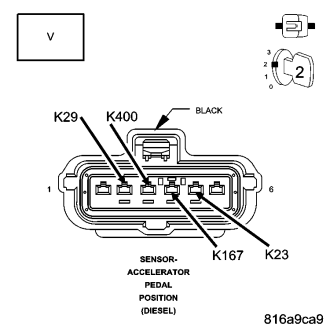
Inspect the Accelerator Pedal Position Sensor for proper travel from the rest position to the fully depressed position.
Turn the ignition on.
With the accelerator pedal in the rest position, use a voltmeter to backprobe the (K23) Accelerator Pedal Position Sensor 1 and the (K29) Accelerator Pedal Position Sensor 2 Signal circuits at the Accelerator Pedal Position Sensor harness connector with the accelerator pedal in the at rest position.
Is the voltage between 0.42 and 0.51 volt for sensor 1 and 0.19 and 0.28 volt for sensor 2?
Yes
- Go To2
No
- Check the wiring and connectors related to the Accelerator Pedal Position Sensor. If OK, replace the Accelerator Pedal Position Sensor.
- Perform the ECM Verification Test Ver. 1 (Refer to 9 - ENGINE - DIAGNOSIS AND TESTING).
2. APP SENSOR
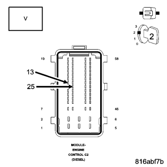
While back probing, measure the voltage of the (K23) Accelerator Pedal Position Sensor Signal 1 and (K29) Accelerator Pedal Position Sensor Signal 2 circuits at the ECM.
Monitor the voltmeter while slowly pressing the accelerator pedal completely down.
Did the voltage for both sensors increase smoothly with pedal travel?
Yes
- Go To3
No
- Replace the Accelerator Pedal Position Sensor in accordance with the Service Information.
- Perform the ECM Verification Test Ver. 1 (Refer to 9 - ENGINE - DIAGNOSIS AND TESTING).
3. APP SENSOR WIDE OPEN THROTTLE VOLTAGE
Using a voltmeter backprobe the Accelerator Pedal Position Sensor harness connector and read the voltage for (K23) Accelerator Pedal Position Sensor 1 and (K29) Accelerator Pedal Position Sensor 2 Signal circuits.
Fully depress the accelerator pedal.
Is the voltage between 4.45 and 4.75 volts for #1 and 2.15 and 2.45 volts for #2?
Yes
- Test Complete.
No
- Check the wiring and connectors related to the APP Sensor. If OK, replace the Accelerator Pedal Position Sensor.
- Perform the ECM Verification Test Ver. 1 (Refer to 9 - ENGINE - DIAGNOSIS AND TESTING).