P0100-MAF SENSOR SIGNAL VOLTAGE TOO HIGH
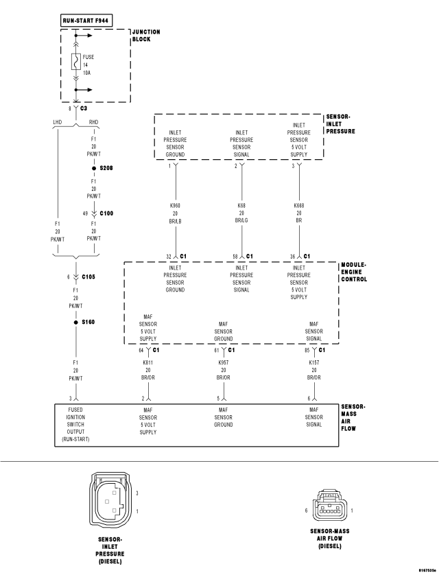
For a complete wiring diagram Refer to Section 8W
- When Monitored:
Engine speed is between 500 and 5000 rpm.
- Set Condition:
The Mass Air Flow Sensor signal is above 800 kg/h for 0.5 seconds.
| Possible Causes |
| ASD RELAY OUTPUT CIRCUIT OPEN |
| ECM - 5-VOLT SUPPLY CIRCUIT |
| MAF SENSOR GROUND OPEN |
| MASS AIRFLOW SENSOR |
| MAF SENSOR 5 VOLT SUPPLY CIRCUIT OPEN |
| MAF SENSOR SIGNAL CIRCUIT OPEN |
| MAF SENSOR 5 VOLT SUPPLY CIRCUIT SHORTED TO THE MAF SENSOR GROUND CIRCUIT |
| MAF SENSOR SIGNAL CIRCUIT SHORTED TO GROUND |
| ECM SENSOR GROUND CIRCUIT OPEN |
| MAF SENSOR 5 VOLT SUPPLY CIRCUIT SHORTED TO GROUND |
| MAF SENSOR SIGNAL CIRCUIT SHORTED TO THE MAF SENSOR GROUND CIRCUIT |
| MAF SENSOR 5 VOLT SUPPLY CIRCUIT SHORTED TO VOLTAGE |
| MAF SENSOR CIRCUIT SHORTED TO VOLTAGE |
| ECM - MAF SENSOR SIGNAL CIRCUIT |
Diagnostic Test
1. VERIFY ACTIVE DTCNOTE: If DTC P0641, P0651 or P0697 is present with this DTC, diagnose DTCs P0641, P0651 or P0697 before diagnosing this DTC.
NOTE: Inspect the turbocharger inlet tube between the MAF Sensor and the turbocharger for damage, restriction or poor connection. Any of these conditions can cause a MAF Plausibility DTC.
NOTE: If the ECM detects and stores a DTC, the ECM also stores the engine/vehicle operating conditions under which the DTC was set. Some of these conditions are displayed on the scan tool at the same time the DTC is displayed.
NOTE: Before erasing stored DTCs, record these conditions. Attempting to duplicate these conditions may assist when checking for an active DTC.
Turn the ignition on.
With the scan tool, erase the ECM DTCs.
Test drive the vehicle.
With the scan tool, read the ECM DTCs.
Does the scan tool display a Mass Air Flow Sensor DTC?
Yes
- Go To2
No
- Refer to the *CHECKING FOR AN INTERMITTENT DTC Diagnostic Procedure. (Refer to 9 - ENGINE - DIAGNOSIS AND TESTING)
2. VERIFY SENSOR 5 VOLT SUPPLY
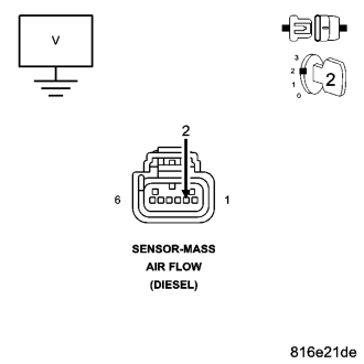
NOTE: A malfunctioning EGR system can cause this DTC to set. Refer to symptom Checking the EGR System in the Driveability category to check EGR system operation.
Turn the ignition off.
Disconnect the MAF Sensor harness connector.
Turn the ignition on.
Measure the voltage of the MAF Sensor 5 Volt Supply circuit in MAF Sensor harness connector.
Is the voltage between 4.8 and 5.2 volts?
Yes
- Go To3
No
- Go To11
3. MAF SENSOR SIGNAL CIRCUIT SHORTED TO VOLTAGE
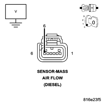
Disconnect the MAF Sensor harness connector.
Disconnect the ECM harness connectors.
Remove the ASD Relay from the PDC.
Connect a jumper wire between cavity 30 and cavity 87 of the ASD Relay connector.
Turn the ignition on.
Measure the voltage of the MAF Sensor Signal circuit.
Is the voltage above 1.0 volt?
Yes
- Repair the MAF Sensor Signal circuit for a short to voltage.
- Perform the ECM Verification Test Ver. 1 (Refer to 9 - ENGINE - DIAGNOSIS AND TESTING).
No
- Go To4
4. MAF SENSOR SIGNAL CIRCUIT OPEN
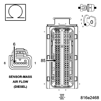
Turn the ignition off.
Disconnect the MAF Sensor harness connector.
Disconnect the ECM harness connectors.
Measure the resistance of the MAF Sensor Signal circuit.
Is the resistance below 10.0 ohms?
Yes
- Go To5
No
- Repair the MAF Sensor Signal circuit for an open
- Perform the ECM Verification Test Ver. 1 (Refer to 9 - ENGINE - DIAGNOSIS AND TESTING).
5. MAF SENSOR SIGNAL CIRCUIT SHORTED TO GROUND
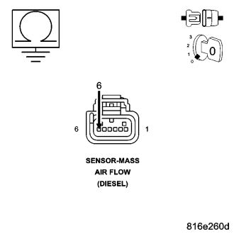
Measure the resistance between ground and the MAF Sensor Signal circuit.
Is the resistance below 1000 ohms?
Yes
- Repair the MAF Sensor Signal circuit for a short to ground.
- Perform the ECM Verification Test Ver. 1 (Refer to 9 - ENGINE - DIAGNOSIS AND TESTING).
No
- Go To6
6. MAF SENSOR SIGNAL CIRCUIT SHORTED TO THE MAF SENSOR GROUND CIRCUIT
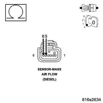
Measure the resistance between the MAF Sensor Signal circuit and the MAF Sensor Ground circuit at of the MAF Sensor harness connector.
Is the resistance below 1000 ohms?
Yes
- Repair the MAF Sensor Signal for a short to MAF Sensor Ground .
- Perform the ECM Verification Test Ver. 1 (Refer to 9 - ENGINE - DIAGNOSIS AND TESTING).
No
- Go To7
7. VERIFY MAF SIGNAL CIRCUIT
Turn the ignition off.
Disconnect the MAF Sensor harness connector.
Connect a jumper wire between MAF Sensor Signal circuit and the 5-volt supply circuit at the MAF Sensor harness connector .
Turn the ignition on.
With the scan tool, read the MAF VOLTS.
Does the scan tool display between 4.0 and 5.5 volts?
Yes
- Go To8
No
- Replace and program the Engine Control Module in accordance with the Service Information.
- Perform the ECM Verification Test Ver. 1 (Refer to 9 - ENGINE - DIAGNOSIS AND TESTING).
8. MAF SENSOR GROUND OPEN
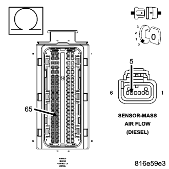
Turn the ignition off.
Disconnect the ECM harness connectors.
Measure the resistance of the MAF Sensor Ground circuit between the MAF Sensor harness connector and the ECM harness connector.
Is the resistance below 10.0 ohms?
Yes
- Go To9
No
- Repair the MAF Sensor Ground circuit for an open.
- Perform the ECM Verification Test Ver. 1 (Refer to 9 - ENGINE - DIAGNOSIS AND TESTING).
9. ECM - SENSOR GROUND OPEN
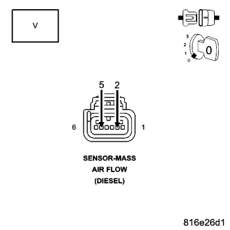
Connect Engine Control Module (ECM) harness connectors.
Turn the ignition on.
Measure the voltage between the 5-volt Supply circuit and the MAF Sensor Ground circuit at the MAF Sensor harness connector.
Is the voltage above 4.5 volts?
Yes
- Go To10
No
- Replace and program the ECM in accordance with the Service Information.
- Perform the ECM Verification Test Ver. 1 (Refer to 9 - ENGINE - DIAGNOSIS AND TESTING).
10. ASD RELAY OUTPUT CIRCUIT OPEN
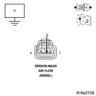
With the scan tool, actuate the ASD Relay.
Measure the voltage of the 12-volt Supply circuit at the MAF Sensor harness connector.
Is the voltage above 10.0 volts?
Yes
- Replace the MAF Sensor.
- Perform ROAD TEST VERIFICATION - VER-2.
No
- Repair the ASD Relay Output circuit for an open.
- Perform the ECM Verification Test Ver. 1 (Refer to 9 - ENGINE - DIAGNOSIS AND TESTING).
11. MAF SENSOR 5 VOLT SUPPLY CIRCUIT OPEN
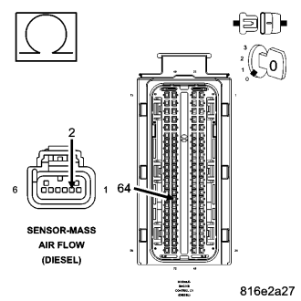
Turn the ignition off.
Disconnect the ECM harness connectors.
Measure the resistance of the MAF Sensor 5 Volt Supply circuit between the MAF Sensor harness connector and the ECM harness connector..
Is the resistance below 10.0 ohms?
Yes
- Go To12
No
- Repair the MAF Sensor 5 Volt Supply circuit for an open.
- Perform the ECM Verification Test Ver. 1 (Refer to 9 - ENGINE - DIAGNOSIS AND TESTING).
12. MAF SENSOR 5 VOLT SUPPLY CIRCUIT SHORTED TO THE MAF SENSOR GROUND CIRCUIT
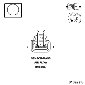
Measure the resistance between the MAF Sensor 5 Volt Supply circuit and the MAF Sensor Ground circuit at the MAF Sensor harness connector.
Is the resistance above 1000 ohms?
Yes
- Go To13
No
- Repair the MAF Sensor 5 Volt Supply circuit for a short to the MAF Sensor Ground circuit.
- Perform the ECM Verification Test Ver. 1 (Refer to 9 - ENGINE - DIAGNOSIS AND TESTING).
13. MAF SENSOR 5 VOLT SUPPLY CIRCUIT SHORTED TO GROUND
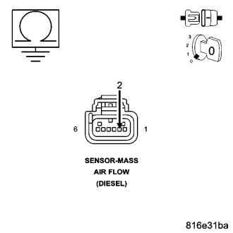
Measure the resistance between ground and the MAF Sensor 5 Volt Supply circuit at the MAF harness connector.
Is the resistance below 1000 ohms?
Yes
- Repair the MAF Sensor 5 Volt Supply circuit for a short to ground.
- Perform the ECM Verification Test Ver. 1 (Refer to 9 - ENGINE - DIAGNOSIS AND TESTING).
No
- Go To14
14. MAF SENSOR 5 VOLT SUPPLY CIRCUIT SHORTED TO VOLTAGE
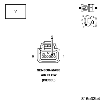
Remove the ASD Relay from the PDC.
Connect a jumper wire between cavity 30 and cavity 87 of the ASD Relay connector.
Turn the ignition on.
Measure the voltage of the MAF Sensor 5 Volt Supply circuit in the ECM harness connector.
Is the voltage above 1.0 volt?
Yes
- Repair the MAF Sensor 5 Volt Supply circuit for a short to voltage.
- Perform the ECM Verification Test Ver. 1 (Refer to 9 - ENGINE - DIAGNOSIS AND TESTING).
No
- Replace and program the Engine Control Module in accordance with the Service Information.
- Perform the ECM Verification Test Ver. 1 (Refer to 9 - ENGINE - DIAGNOSIS AND TESTING).