P0836-TRANSFER CASE POSITION SIGNAL VOLTAGE TOO LOW
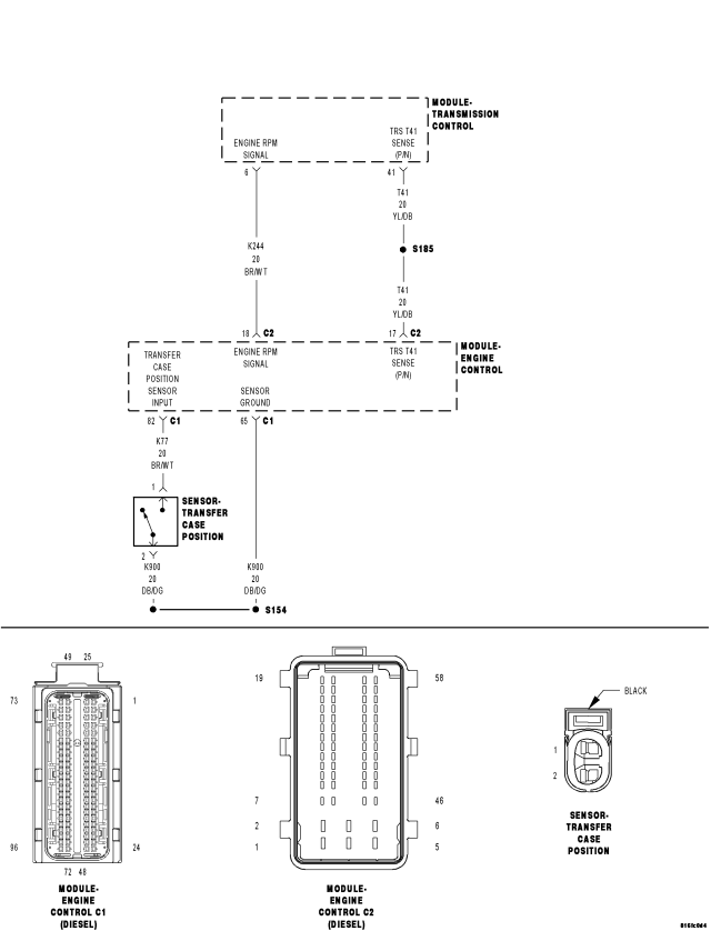
For a complete wiring diagram Refer to Section 8W
- When Monitored:
With the ignition on. No other T-Case Position Sensor DTC's present.
- Set Condition:
The Transfer Case Position Sensor Signal is below 0.14 for 0.5 second.
| Possible Causes |
| TRANSFER CASE POSITION SENSOR |
| INTERMITTENT WIRING AND CONNECTORS |
| TRANSFER CASE POSITION SENSOR SIGNAL CIRCUIT OPEN |
| TRANSFER CASE POSITION SENSOR SIGNAL CIRCUIT SHORT TO GROUND |
| TRANSFER CASE POSITION SENSOR SIGNAL CIRCUIT SHORT TO VOLTAGE |
| TRANSFER CASE POSITION SENSOR SIGNAL CIRCUIT SHORT TO SENSOR GROUND CIRCUIT |
| ENGINE CONTROL MODULE |
Diagnostic Test
1. CHECKING FOR CURRENT DTCNOTE: If the ECM detects and stores a DTC, the ECM also stores the engine/vehicle operating conditions under which the DTC was set. Some of these conditions are displayed on the DRB at the same time the DTC is displayed.
NOTE: Before erasing stored DTCs, record these conditions. Attempting to duplicate these conditions may assist when checking for an active DTC.
NOTE: The vehicle speedometer must be operational for the result of this test to be valid.
With the DRBIII®, record and erase DTCs.
Start the engine and cycle the Transfer Case through all positions.
With the DRBIII®, read the ECM DTCs.
Does the DRBIII® display this DTC?
Yes
- Go To2
No
- Go To7
2. TRANSFER CASE POSITION SENSOR SIGNAL CIRCUIT SHORT TO VOLTAGE
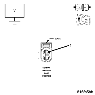
Turn the ignition off to the lock position.
Disconnect the ECM harness connectors.
Disconnect the Transfer Case Position Sensor harness connector.
Remove the ASD Relay.
Connect a jumper wire between cavities 30 and 87 of the ASD Relay connector in the PDC.
Turn the ignition on.
Measure the voltage of the Transfer Case Position Sensor Signal circuit.
Is the voltage above 1.0 volt?
Yes
- Repair the Transfer Case Position Sensor Signal circuit for a short to voltage.
- Perform the ECM Verification Test Ver. 1 (Refer to 9 - ENGINE - DIAGNOSIS AND TESTING).
No
- Go To3
3. TRANSFER CASE POSITION SENSOR SIGNAL CIRCUIT OPEN
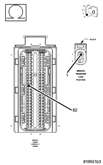
Turn the ignition off to the lock position.
Remove the jumper wire and install the ASD Relay.
Measure the resistance of the Transfer Case Position Sensor Signal circuit.
Is the resistance below 10.0 ohms?
Yes
- Go To4
No
- Repair the Transfer Case Position Sensor Signal circuit for an open.
- Perform the ECM Verification Test Ver. 1 (Refer to 9 - ENGINE - DIAGNOSIS AND TESTING).
4. TRANSFER CASE POSITION SENSOR SIGNAL CIRCUIT SHORT TO GROUND
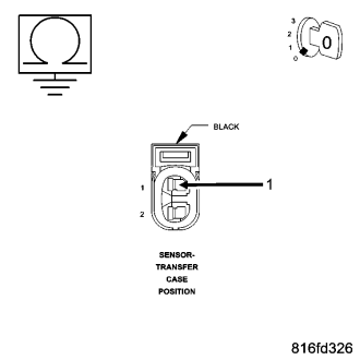
Measure the resistance between ground and the Transfer Case Position Sensor Signal circuit.
Is the resistance below 1000.0 ohms?
Yes
- Repair the Transfer Case Position Sensor Signal circuit for a short to ground.
- Perform the ECM Verification Test Ver. 1 (Refer to 9 - ENGINE - DIAGNOSIS AND TESTING).
No
- Go To5
5. TRANSFER CASE POSITION SENSOR SIGNAL CIRCUIT SHORT TO SENSOR RETURN CIRCUIT
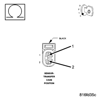
Measure the resistance between the Transfer Case Position Sensor circuit and the Sensor Ground circuit.
Is the resistance below 1000.0 ohms?
Yes
- Repair the Transfer Case Position Sensor Signal circuit for a short to the Sensor Ground circuit.
- Perform the ECM Verification Test Ver. 1 (Refer to 9 - ENGINE - DIAGNOSIS AND TESTING).
No
- Go To6
6. TRANSFER CASE POSITION SENSOR
Reconnect the ECM harness connectors.
Reconnect the Transfer Case Position Sensor harness connector.
Turn the ignition on.
With the DRBIII® read the T-case Sensor
Observe the T-case volts on the DRB while moving the transfer case selector lever in each of the transfer case positions.
NOTE: When shifting the transfer case selector to each position, the Sensor voltage should result in the following voltages: 2WD 2.64 - 2.80, 4WD Part Time 1.96 - 2.12, 4WD Full Time 1.39 - 1.55, Neutral 0.80 - 0.96, 4WD Low 0.21 - 0.37,
Does each position provide the correct voltage?
Yes
- Replace and program the ECM in accordance with the Service Information.
- Perform the ECM Verification Test Ver. 1 (Refer to 9 - ENGINE - DIAGNOSIS AND TESTING).
No
- Replace the Transfer Case Position Sensor.
- Perform the ECM Verification Test Ver. 1 (Refer to 9 - ENGINE - DIAGNOSIS AND TESTING).
7. INTERMITTENT WIRING AND CONNECTORS
The conditions necessary to set this DTC are not present at this time.
Using the schematics as a guide, inspect the wiring and connectors specific to this circuit.
Wiggle the wiring while checking for shorts and open circuits.
Were there any problems found?
Yes
- Repair as necessary.
- Perform the ECM Verification Test Ver. 1 (Refer to 9 - ENGINE - DIAGNOSIS AND TESTING).
No
- Test Complete.