P0585-SPEED CONTROL SWITCH 1/2 CORRELATION
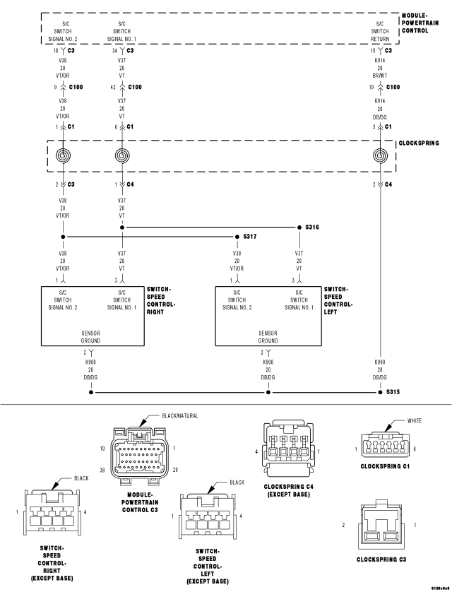
For a complete wiring diagram Refer to Section 8W.
- When Monitored:
Ignition on.
- Set Condition:
Cruise Switch inputs are not coherent with each other. Example: PCM is reading Switch No.1 as Accel and Switch No.2 as Coast at the same time. One trip fault.
| Possible Causes |
| S/C SWITCH SIGNAL CIRCUITS SHORTED TO BATTERY VOLTAGE |
| RESISTANCE IN THE S/C SWITCH SIGNAL CIRCUITS |
| RESISTANCE IN THE (K914) SWITCH RETURN CIRCUIT |
| S/C SWITCH SIGNAL CIRCUITS SHORTED TO THE (K914) SWITCH RETURN CIRCUIT |
| (V37) S/C SWITCH NO.1 SIGNAL CIRCUIT SHORTED TO THE (V38) S/C SWITCH NO.2 SIGNAL CIRCUIT |
| S/C SWITCH SIGNAL CIRCUITS SHORTED TO GROUND |
| CLOCKSPRING |
| SPEED CONTROL ON/OFF SWITCH |
| SPEED CONTROL RESUME/ACCEL SWITCH |
| PCM |
Always perform the Pre-Diagnostic Troubleshooting procedure before proceeding. (Refer to 9 - ENGINE - DIAGNOSIS AND TESTING).
Diagnostic Test
1. ACTIVE DTCNOTE: This DTC is a two trip fault. If the scan tool indicates a one trip failure, the possible cause may have been the customer pressing both switches simultaneously. Test drive the vehicle and activate the Speed Control system. If the DTC matures to an active fault a repair is necessary.
Ask the customer if it is possible that two buttons were pressed at the same time before this DTC set. If this is the case, no repair is necessary.
Start the engine.
Allow the engine to reach normal operating temperature.
With a scan tool, select View DTCs.
NOTE: It may be necessary to drive the vehicle to meet the conditions to set this DTC, try to repeat the conditions in which the fault originally set by reviewing the Freeze Frame data.
Is the DTC Active or Pending at this time?
Yes
- Go To 2
No
- Refer to the INTERMITTENT CONDITION Diagnostic Procedure.
- Perform the POWERTRAIN VERIFICATION TEST. (Refer to 9 - ENGINE - STANDARD PROCEDURE)
2. SPEED CONTROL ON/OFF SWITCH
With the scan tool, monitor the Speed Control Switch voltage.
Disconnect the Speed Control On/Off Switch harness connector.
Did the voltage change to above 4.8 volts?
Yes
- Replace the Speed Control On/Off Switch.
- Perform the POWERTRAIN VERIFICATION TEST. (Refer to 9 - ENGINE - STANDARD PROCEDURE)
No
- Go To 3
3. SPEED CONTROL RESUME/ACCEL SWITCH
With the scan tool, monitor the Speed Control Switch voltage.
Disconnect the Speed Control Resume/Accel Switch harness connector.
Did the voltage change to above 4.8 volts?
Yes
- Replace the Speed Control Resume/Accel Switch.
- Perform the POWERTRAIN VERIFICATION TEST. (Refer to 9 - ENGINE - STANDARD PROCEDURE)
No
- Go To 4
4. SPEED CONTROL SWITCHES
Turn the ignition off.
Remove and disconnect the Speed Control Switches from the steering wheel per Service Information.
Measure the resistance across each Speed Control Switch.
Monitor the ohmmeter while pressing each function button on each switch.
The following resistance specs are taken between terminals (V38) S/C Switch No.2 Signal and (K914) S/C Switch Return circuits of the Switch when holding the switch button in the following position.
Not pressing any switch - 20.5 kohms
On/Off - 8.87 kohms
Set - 0.825 kohms
Coast - 0.47 kohms
Cancel - 3.92 kohms
Resume/Accel - 1.87 kohms
The following resistance specs are taken between terminals (V37) S/C Switch No.1 Signal and (K914) S/C Switch Return circuits of the Switch when holding the switch button in the following position
Not pressing any switch - 20.5 kohms
On/Off - 0.47 kohms
Set - 5.49 kohms
Coast - 2.94 kohms
Cancel - 1.24 kohms
Resume/Accel - 15.4 kohms
Does the function on the Speed Control Switches have the correct resistance value?
Yes
- Go To 5
No
- Replace the Speed Control Switch that had the incorrect resistance value.
- Perform the POWERTRAIN VERIFICATION TEST. (Refer to 9 - ENGINE - STANDARD PROCEDURE)
5. S/C SWITCH SIGNAL CIRCUIT SHORTED TO BATTERY VOLTAGE
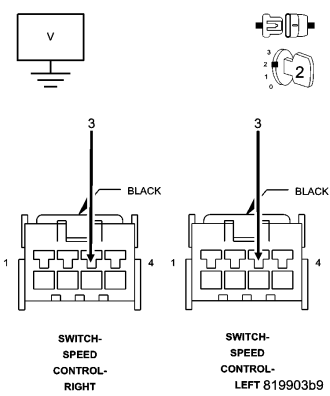
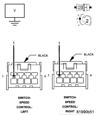
Disconnect the C3 PCM harness connector.
Measure the voltage on the (V37) and (V38) S/C Switch Signal circuits at both Speed Control harness connectors.
Is the voltage above 5.0 volts?
Yes
- Repair the short to battery voltage in the (V37) or (V38) S/C Switch Signal circuit.
- Perform the POWERTRAIN VERIFICATION TEST. (Refer to 9 - ENGINE - STANDARD PROCEDURE)
No
- Go To 6
6. CLOCKSPRING
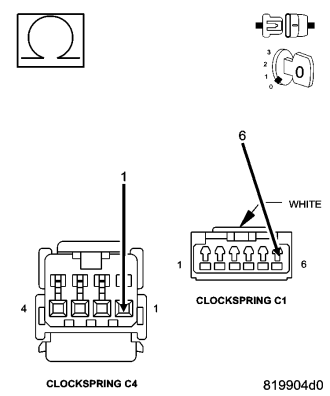
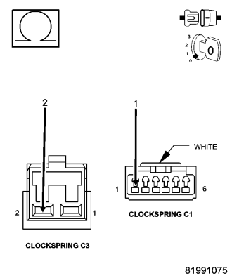
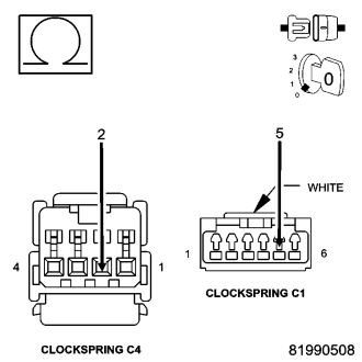
Turn the ignition off.
Disconnect the C1 and C3 Clockspring harness connectors per Service Information.
Measure the resistance of the (V37) and (V38) S/C Switch Signal circuits between the C1 and C3 Clockspring connectors.
Measure the resistance of the (K914) Switch Return circuit between the C1 and C3 Clockspring harness connectors.
Is the resistance above 5.0 ohms for any one of the measurements?
Yes
- Replace the Clockspring per Service Information.
- Perform the POWERTRAIN VERIFICATION TEST. (Refer to 9 - ENGINE - STANDARD PROCEDURE)
No
- Go To 7
NOTE: Connect the Clockspring harness connectors per Service Information before continuing.
7. S/C SWITCH SIGNAL CIRCUIT OPEN
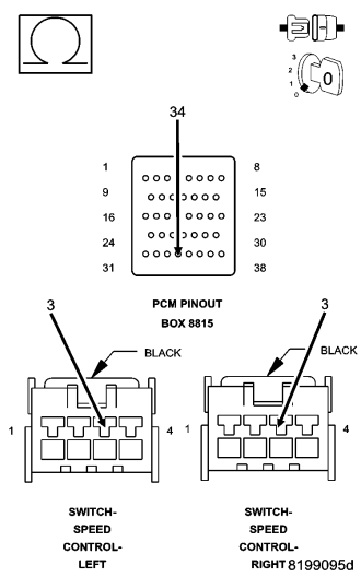
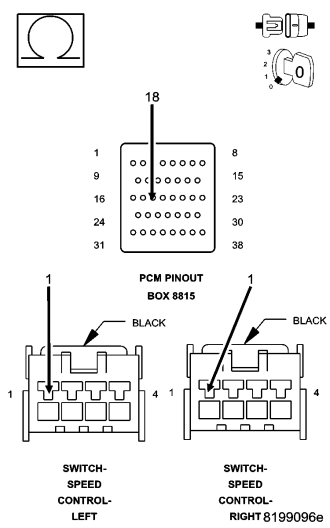
CAUTION: Do not probe the PCM harness connectors. Probing the PCM harness connectors will damage the PCM terminals resulting in poor terminal to pin connection. Install Miller Special Tool #8815 to perform diagnosis.
Measure the resistance of the (V37) and (V38) S/C Switch Signal circuits from both Speed Control harness connectors to the appropriate terminals of special tool #8815.
Is the resistance below 5.0 ohms for each measurement?
Yes
- Go To 8
No
- Repair the excessive resistance in the (V37) or (V38) S/C Switch Signal circuit.
- Perform the POWERTRAIN VERIFICATION TEST. (Refer to 9 - ENGINE - STANDARD PROCEDURE)
8. (K914) SWITCH RETURN CIRCUIT OPEN
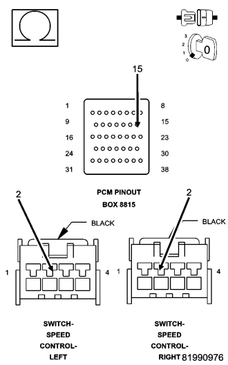
NOTE: The measurement must be taken from both Speed Control Switch harness connectors.
Measure the resistance of the (K914) Switch Return circuit from both Speed Control harness connector to the appropriate terminal of special tool #8815.
Is the resistance below 5.0 ohms for both measurements?
Yes
- Go To 9
No
- Repair the excessive resistance in the (K914) Switch Return circuit.
- Perform the POWERTRAIN VERIFICATION TEST. (Refer to 9 - ENGINE - STANDARD PROCEDURE)
9. S/C SWITCH SIGNAL CIRCUITS SHORTED TO THE (K914) SWITCH RETURN CIRCUIT

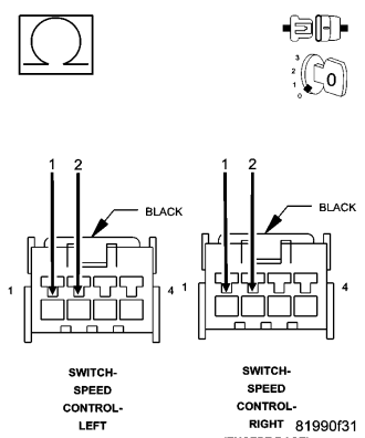
Measure the resistance between the (K914) Switch Return circuit and both of the (V37) and (V38) S/C Switch Signal circuits in the S/C Switch harness connector.
Is the resistance below 5.0 ohms?
Yes
- Repair the short between the (K914) Switch Return circuit and the (V37) or (V38) S/C Switch Signal circuit.
- Perform the POWERTRAIN VERIFICATION TEST. (Refer to 9 - ENGINE - STANDARD PROCEDURE)
No
- Go To 10
10. (V37 S/C SWITCH NO.1 SIGNAL CIRCUIT SHORTED TO THE (V38) S/C SWITCH NO.2 SIGNAL CIRCUIT
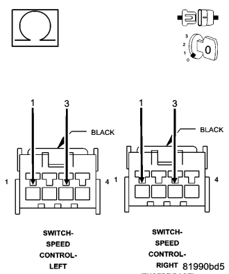
Measure the resistance between the (V37) S/C Switch No.1 Signal circuit and the (V38) S/C Switch No.2 Signal circuit at both Speed Control harness connectors.
Is the resistance below 100 ohms for each circuit?
Yes
- Repair the short between the (V38) S/C Switch No.2 Signal circuit and the (V37) S/C Switch No.1 Signal circuit.
- Perform the POWERTRAIN VERIFICATION TEST. (Refer to 9 - ENGINE - STANDARD PROCEDURE)
No
- Go To 11
11. S/C SWITCH SIGNAL CIRCUITS SHORTED TO GROUND
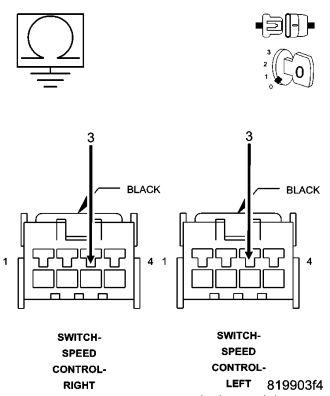
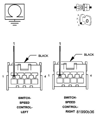
Measure the resistance between ground and the (V37) and (V38) S/C Switch Signal circuits at both S/C Switch harness connectors.
Is the resistance below 100 ohms?
Yes
- Repair the short to ground in the (V37) or (V38) S/C Switch Signal circuit.
- Perform the POWERTRAIN VERIFICATION TEST. (Refer to 9 - ENGINE - STANDARD PROCEDURE)
No
- Go To 12
12. SPEED CONTROL SWITCH VOLTAGE VALUES
Allow the engine to idle.
With a scan tool, monitor the S/C Switch voltage readings.
| SWITCH POSITION | SWITCH No.1 VOLTAGE VALUE | SWITCH No.2 VOLTAGE VALUE |
| NO SWITCHES PRESSED | 4.31 to 4.78 volts | 4.31 to 4.78 volts |
| ON/OFF PRESSED | 0.59 to 1.13 volts | 3.53 to 3.92 volts |
| RES/ACCEL PRESSED | 3.88 to 4.17 volts | 2.04 to 2.47 volts |
| SET PRESSED | 3.16 to 3.56 volts | 1.17 to 1.56 volts |
| COAST PRESSED | 2.57 to 2.94 volts | 0.77 to 1.09 volts |
| CANCEL PRESSED | 1.59 to 1.99 volts | 2.84 to 3.25 volts |
Take these same voltage measurements with a voltmeter by back probing the (V37) S/C Switch No.1 Signal circuit and the (V38) S/C Switch No.2 Signal circuit at the switches.
Compare the voltage readings on the voltmeter to what the scan tool displayed.
Are the voltage readings out of the listed specification and is there less than a 0.2 of a volt difference between the voltmeter switch values and the scan tool switch values?
Yes
- Replace the Speed Control Switch.
- Perform the POWERTRAIN VERIFICATION TEST. (Refer to 9 - ENGINE - STANDARD PROCEDURE)
No
- Go To 13
13. PCM
NOTE: Before continuing, check the PCM harness connector terminals for corrosion, damage, or terminal push out. Repair as necessary.
Using the schematics as a guide, inspect the wire harness and connectors. Pay particular attention to all Power and Ground circuits.
Were there any problems found?
Yes
- Repair as necessary.
- Perform the POWERTRAIN VERIFICATION TEST. (Refer to 9 - ENGINE - STANDARD PROCEDURE)
No
- Replace and program the Powertrain Control Module per Service Information.
- Perform the POWERTRAIN VERIFICATION TEST. (Refer to 9 - ENGINE - STANDARD PROCEDURE)