HEATER - FUEL
DESCRIPTION
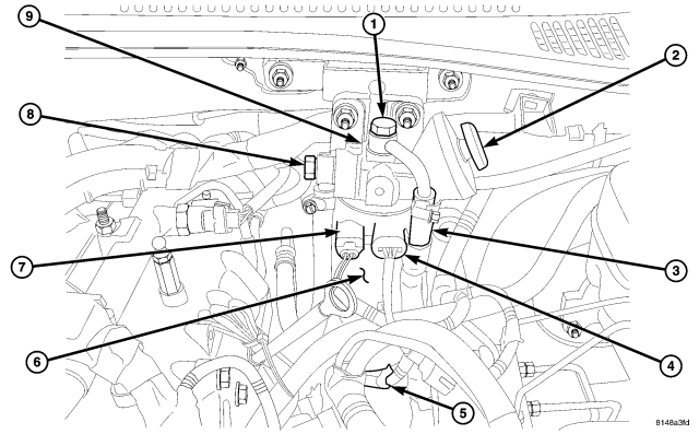
The fuel heater is used to prevent diesel fuel from waxing and plugging the fuel filter during cold weather operation. The fuel heater is located in the fuel filter/water separator assembly head, next to the fuel temperature sensor .
OPERATION
The element inside the heater assembly is made of a Positive Temperature Coefficient (PTC) material, and has power applied to it by the fuel heater relay anytime the ignition key is in the “on” position. PTC material has a high resistance to current flow when its temperature is high, which means that it will not generate heat when the temperature is above a certain value. When the temperature is below 7°C (45° F), the resistance of the PTC element is lowered, and allows current to flow through the fuel heater element warming the fuel. When the temperature is above 29°C (85° F), the PTC element's resistance rises, and current flow through the heater element stops .
Voltage to operate the fuel heater is supplied from the glow plug module, through the fuel heater relay, when the ECM senses the ignition (key) switch.
REMOVAL
WARNING: Store fuel in approved and properly marked containers. Wear safety goggles and adequate protective clothing when servicing fuel system.
1. Disconnect negative battery cable.
2. Disconnect fuel heater, fuel temperature and water in fuel (WIF) sensor electrical connectors .
3. Drain fuel filter/water separator assembly into a suitable and appropriately marked container by loosening the WIF at the bottom of fuel filter.
NOTE: Care must be taken to identify the fuel supply and return hoses before removal from the fuel filter housing. They can easily be crossed during installation and lead to a no start condition.
4. Paint mark and remove the fuel inlet and outlet hoses .
5. Remove fuel supply and return hose from the housing.
6. Remove the fuel filter housing fasteners and housing.
INSTALLATION
1. Install fuel filter/water separator assembly. Tighten retaining fasteners to 24.5 N·m (18 ft.lbs.) .
NOTE: Care must be taken when installing the fuel lines to assure proper routing. The lines can easily be crossed and cause a no start condition after the repair.
2. Connect the fuel supply and return lines. Tighten clamps to 7 N·m (62 in. lbs.) .
3. Connect fuel heater, WIF and fuel temperature sensor electrical connectors.
4. Prime fuel system using the fuel priming plunger . (Refer to 14 - FUEL SYSTEM - STANDARD PROCEDURE).
5. Connect negative battery cable.