SENSOR - FUEL LEVEL SENDING UNIT
DESCRIPTION
The fuel gauge sending unit (fuel level sensor) is attached to the side of the lower fuel tank module. The sending unit consists of a float, an arm, and a variable resistor track (card).
OPERATION
For Fuel Gauge Operation: A constant current source of approximately 32 milliamps is supplied to the resistor track on the fuel gauge sending unit. This is fed directly from the Engine Control Module (ECM). NOTE: For diagnostic purposes, this 12V power source can only be verified with the circuit opened (fuel tank module electrical connector unplugged). With the connectors plugged, output voltages will vary from about 0.6 volts at FULL, to about 8.6 volts at EMPTY (about 8.6 volts at EMPTY for Jeep models, and about 7.0 volts at EMPTY for Dodge Truck models). The resistor track is used to vary the voltage (resistance) depending on fuel tank float level. As fuel level increases, the float and arm move up, which decreases voltage. As fuel level decreases, the float and arm move down, which increases voltage. The varied voltage signal is returned back to the ECM through the sensor return circuit.
Both of the electrical circuits between the fuel gauge sending unit and the ECM are hard-wired (not multi-plexed). After the voltage signal is sent from the resistor track, and back to the ECM, the ECM will interpret the resistance (voltage) data and send a message across the multi-plex bus circuits to the instrument panel cluster. Here it is translated into the appropriate fuel gauge level reading. Refer to Instrument Panel for additional information.
DIAGNOSIS AND TESTING - FUEL LEVEL SENDING UNIT
The fuel level sending unit contains a variable resistor (track). As the float moves up or down, electrical resistance will change. Refer to Instrument Panel and Gauges for Fuel Gauge testing. To test the gauge sending unit only, it must be removed from vehicle. The unit is a separate part of the lower fuel tank module section. Refer to Fuel Tank Module Removal/Installation for procedures (remove only the upper section of the fuel pump module). Measure the resistance across the sending unit terminals. With float in up position, resistance should be 20 ohms (+/- 5%). With float in down position, resistance should be 220 ohms (+/- 5%).
REMOVAL
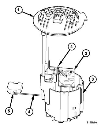
The fuel level sending unit (fuel level sensor) (2) and float assembly (4) and (5) are located on the fuel tank module.
1. Remove fuel tank module from fuel tank (Refer to 14 - FUEL SYSTEM/FUEL DELIVERY/FUEL TANK MODULE - REMOVAL) .
2. To remove sending unit from tank module, lift on plastic locking tab while sliding sending unit upwards.
3. Disconnect electrical connectors from fuel tank module. Separate necessary sending unit wiring.
INSTALLATION
1. Connect necessary wiring into electrical connectors.
2. Position sending unit (2) to tank module. Slide and snap into place until tab engages.
3. Install fuel tank module into fuel tank.