INJECTOR - FUEL
OPERATION
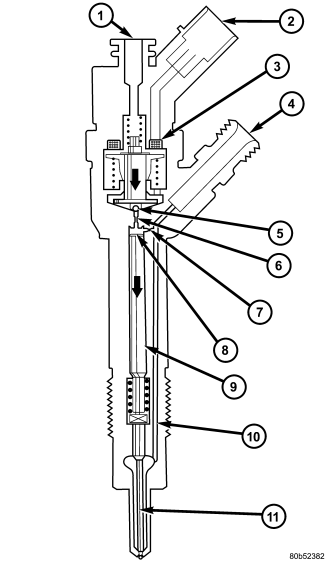
(Refer to 14 - FUEL SYSTEM - WARNING) The injector operation can be subdivided into four operating states with the engine running and the high-pressure pump generating pressure:
- Injector closed (with high pressure applied)
- Injector opens (start of injection)
- Injector opened fully
- Injector closes (end of injection)
Injector closed (with high pressure applied)
With the injector closed (at-rest state), the solenoid valve is not energized and is therefore closed. With the bleed orifice closed, the valve spring forces the armature's ball onto the bleed-orifice seat. The rail's high pressure build up in the valve control chamber, and the same pressure is also present in the nozzle's chamber volume. The rail pressure applied at the control plunger's end face, together with the force of the nozzle spring, maintain the nozzle in the closed position against the opening forces applied to its pressure stage .
Injector opens (start of injection)
The solenoid valve is energized with the pickup current which serves to ensure that it open quickly. The force exerted by the triggered solenoid now exceeds that of the valve spring and the armature opens the bleed orifice. Almost immediately, the high-level pick-up current is reduced to the lower holding current required for the electromagnet. This is possible due to the magnetic circuit's air gap now being smaller. When the bleed orifice opens, fuel can flow from the valve control chamber into the cavity situated above it, and from there via the fuel return to the tank. The bleed orifice prevents complete pressure balance, and the pressure in the valve control chamber sinks as a result. This leads to the pressure in the valve-control chamber being lower than that in the nozzle's chamber volume which is still at the same pressure level as the rail. The reduced pressure in the valve-control chamber causes a reduction in the force exerted on the control plunger, the nozzle needle opens as a result, and injection starts .
Injector opens fully
The control plunger reaches its upper stop where it remains supported by a cushion of fuel which is generated by the flow of fuel between the bleed and feed orifices. The injector nozzle has now opened fully, and the fuel is injected into the combustion chamber at a pressure almost equal to that in the fuel rail .
Injector closes (end of injection)
As soon as the solenoid valve is no longer triggered, the valve spring forces the armature downwards and the ball closes the bleed orifice. The armature is a 2–piece design. Here, although the armature plate is guided by a driver shoulder in its downward movement, it can “overspring” with the return spring so that it exerts no downwards-acting forces on the armature and the ball. The closing of the bleed orifice lead to pressure build up in the control chamber via the input from the feed orifice. This pressure is the same as that in the rail and exerts an increased force on the control plunger through its end face. This force, together with that of the spring, now exceeds the force exerted by the chamber volume and the nozzle needle closes. Injection ceases as soon as the nozzle needle comes up against its bottom stop again .
REMOVAL
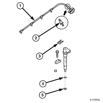
1. Review the High Pressure Fuel System Warning (Refer to 14 - FUEL SYSTEM - WARNING).
2. Disconnect negative battery cable.
3. Remove engine cover (Refer to 9 - ENGINE - REMOVAL).
4. Disconnect injector electrical connector.
CAUTION: Repeated mounting of the retaining ring is not permitted.
5. Remove fuel return line from injector .
6. Remove fuel injector high pressure line (Refer to 14 - FUEL SYSTEM - WARNING) .
7. Remove fuel injector retainer and retaining bolt .
8. Using compressed air, clean surface area in and around injector bore to prevent foreign material from falling into the injector bore, after injector removal.
NOTE: DO NOT use a wire brush to clean the fuel injector or nozzle. Possible restriction of the injector needle may result.
9. Remove fuel injector from cylinder head .
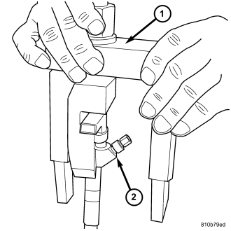
CAUTION: If the fuel injectors will not come out of the cylinder head, perform the following steps to prevent damaging other components.
10. Assemble and install Injector extractor special tool VM 9075A on to injector and cylinder head .
INSTALLATION
WARNING: High - pressure lines deliver diesel fuel under extreme pressure from the injection pump to the fuel injectors. This may be as high as 1600 bar (23,200 psi.). Use extreme caution when inspecting for high - pressure fuel leaks. Fuel under this amount of pressure can penetrate skin causing personal injury or death. Inspect for high - pressure fuel leaks with a sheet of cardboard. Wear safety goggles and adequate protective clothing when servicing fuel system.
NOTE: DO NOT use a brush to clean around the injector nozzle. DO NOT lubricate area around injector nozzle. The injector may become restricted with debris.
NOTE: Be sure a new copper washer/seal is installed on end of injector and the old seal is removed, before installing in cylinder head.
NOTE: Apply anti seize compound to injector body.
1. Install fuel injector in cylinder head with new seal and O-ring.
2. Install fuel injector retainer and bolt . Torque bolt to 32.4 N·m (24 ft. lbs.)..
3. Install fuel injector high pressure line.
4. Install fuel return line to injector .
5. Connect fuel injector electrical connector.
6. Install engine cover and bracket assembly (Refer to 9 - ENGINE COVER - INSTALLATION) .
7. Connect negative battery cable.
8. Perform the injector classification procedure with the scan tool (Refer to 14 - FUEL SYSTEM/FUEL INJECTION/FUEL INJECTOR - STANDARD PROCEDURE).
9. Start the engine, allow to warm, Turn Off the Ignition, Inspect for leaks.