SENSOR - BOOST PRESSURE
- DESCRIPTION
- OPERATION
- DIAGNOSIS AND TESTING - BOOST PRESSURE/INTAKE AIR TEMPERATURE SENSOR
- REMOVAL
- INSTALLATION
DESCRIPTION
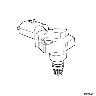
The boost pressure/intake air temperature sensor is mounted to the top of the intake manifold. The sensor allows the ECM to monitor air pressure within the intake manifold. This sensor is also used to monitor the intake air temperature .
OPERATION
When the intake manifold pressure is low sensor voltage output is 0.25-1.8 volts at the ECM. When the intake manifold pressure is high due to turbo boost, sensor voltage output is 2.0-4.7 volts. The sensor receives a 5-volts reference from the ECM. Sensor ground is also provides by the ECM. The ECM uses boost pressure combined with intake air temerature to determine the volume of air entering the engine.
DIAGNOSIS AND TESTING - BOOST PRESSURE/INTAKE AIR TEMPERATURE SENSOR
If the boost pressure sensor fails, the ECM records a DTC into memory and continues to operate the engine in one of the three limp-in modes. When the ECM is operating in this mode, a loss of power will be present, as if the turbocharger was not operating. The best method for diagnosing faults with the boost pressure sensor is with the scan tool. Refer to the Diesel Powertrain Diagnostic Manual for more information.
REMOVAL
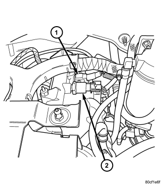
1. Disconnect negative battery cable.
2. Remove engine cover and bracket assembly (Refer to 9 - ENGINE COVER - REMOVAL) .
3. Disconnect sensor electrical connector .
4. Remove retaining bolts and remove sensor (1) from cylinder head cover/intake manifold.
INSTALLATION
1. Install sensor (1) and retaining bolts into cylinder head cover/intake manifold. Torque to 5.4 N·m (48 in. lbs.)..
2. Connect sensor electrical connector.
3. Install engine cover and bracket assembly (Refer to 9 - ENGINE - INSTALLATION).
4. Connect negative battery cable.