DIAGNOSIS AND TESTING
- REAR DEFOGGER RELAY CONTROL CIRCUIT SHORT TO VOLTAGE
- REAR DEFOGGER RELAY CONTROL CIRCUIT OPEN/SHORT TO GROUND
- *REAR WINDOW DEFOGGER INOPERATIVE
REAR DEFOGGER RELAY CONTROL CIRCUIT SHORT TO VOLTAGE
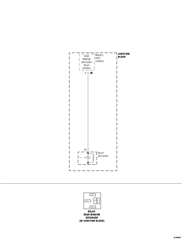
For a complete wiring diagram Refer to Section 8W.
- When Monitored:
With the ignition on.
- Set Condition:
When the BCM detects unwanted voltage on the rear window defogger control circuit.
| Possible Causes |
| CODE ACTIVE |
| REAR DEFOGGER RELAY SHORTED |
| JUNCTION BLOCK - REAR DEFOGGER RELAY CONTROL CIRCUIT SHORT TO VOLTAGE |
| BODY CONTROL MODULE |
Diagnostic Test
1. CHECK TROUBLE CODETurn the ignition on.
With the scan tool, erase DTCs.
Attempt to operate the Rear Window Defogger.
With the scan tool, read DTCs.
Does the scan tool display REAR WINDOW DEFOGGER RELAY CONTROL CIRCUIT SHORT TO VOLTAGE?
Yes
- Go To2
No
- Problem is intermittent and not present at this time. Using the wiring diagram/schematic as a guide, inspect the wiring and connectors and repair as necessary.
- Perform BODY VERIFICATION TEST - VER 1. (Refer to 8 - ELECTRICAL/ELECTRONIC CONTROL MODULES - STANDARD PROCEDURE).
2. RELAY SHORTED
Remove the Rear Window Defogger Relay from the Junction Block.
Install a substitute relay in place of the Rear Window Defogger Relay.
With the scan tool, erase DTCs.
Attempt to operate the Rear Window Defogger.
With the scan tool, read DTCs.
Does the scan tool display REAR WINDOW DEFOGGER RELAY CONTROL CIRCUIT SHORT TO VOLTAGE?
Yes
- Go To3
No
- Replace the original relay.
- Perform BODY VERIFICATION TEST - VER 1. (Refer to 8 - ELECTRICAL/ELECTRONIC CONTROL MODULES - STANDARD PROCEDURE).
3. JUNCTION BLOCK - REAR WINDOW DEFOGGER RELAY CONTROL CIRCUIT SHORT TO VOLTAGE
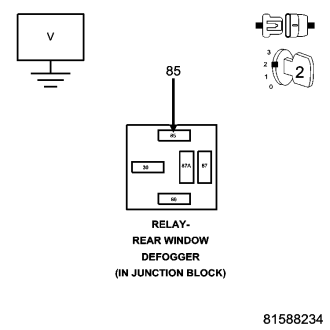
Turn the ignition off.
Remove the Rear Window Defogger Relay from the Junction Block.
Remove the Body Control Module from the Junction Block.
NOTE: Ensure the Junction Block connectors are reconnected at this time.
Turn the ignition on.
Measure the voltage of the Rear Window Defogger Relay Control circuit in the relay connector of the Junction Block.
Is there any voltage present?
Yes
- Replace the Junction Block.
- Perform BODY VERIFICATION TEST - VER 1. (Refer to 8 - ELECTRICAL/ELECTRONIC CONTROL MODULES - STANDARD PROCEDURE).
No
- Replace the Body Control Module.
- Perform BODY VERIFICATION TEST - VER 1. (Refer to 8 - ELECTRICAL/ELECTRONIC CONTROL MODULES - STANDARD PROCEDURE).
REAR DEFOGGER RELAY CONTROL CIRCUIT OPEN/SHORT TO GROUND
For a complete wiring diagram Refer to Section 8W.
Diagnostic Test
- When Monitored:
With the ignition on.
- Set Condition:
When the BCM detects no voltage on the Rear Window Defogger Control circuit due to an open or short to ground.
| Possible Causes |
| JUNCTION BLOCK FUSE 39 |
| CODE ACTIVE |
| RELAY OPEN OR SHORTED |
| JUNCTION BLOCK - REAR WINDOW DEFOGGER RELAY CONTROL SHORT TO GROUND |
| FUSED IGNITION SWITCH OUTPUT CIRCUIT OPEN |
| JUNCTION BLOCK - REAR WINDOW DEFOGGER RELAY CONTROL OPEN |
| BODY CONTROL MODULE |
Diagnostic Test
1. CHECK TROUBLE CODETurn the ignition on.
With the scan tool, erase DTCs.
Attempt to operate the Rear Window Defogger.
With the scan tool, read DTCs.
Does the scan tool display REAR WINDOW DEFOGGER RELAY CONTROL CIRCUIT OPEN/SHORT TO GROUND?
Yes
- Go To2
No
- Problem is intermittent and not present at this time. Using the wiring diagram/schematic as a guide, inspect the wiring and connectors and repair as necessary. Ensure the relay is completely plugged in.
- Perform BODY VERIFICATION TEST - VER 1. (Refer to 8 - ELECTRICAL/ELECTRONIC CONTROL MODULES - STANDARD PROCEDURE).
2. JUNCTION BLOCK FUSE 39
Check Junction Block fuse 39.
Is the fuse open.
Yes
- Check for a short to ground and replace the Junction Block fuse.
- Perform BODY VERIFICATION TEST - VER 1. (Refer to 8 - ELECTRICAL/ELECTRONIC CONTROL MODULES - STANDARD PROCEDURE).
No
- Go To3
3. FUSED IGNITION SWITCH OUTPUT CIRCUIT OPEN
Turn the ignition on.
Using a 12-volt test light connected to ground, check the Fused Ignition Switch Output circuit at Fuse 39.
The test light must illuminate brightly. Compare the brightness to that of a direct connection to the battery.
Does the test light illuminate brightly?
Yes
- Go To4
No
- Repair the open Fused Ignition Switch Output circuit as necessary.
- Perform BODY VERIFICATION TEST - VER 1. (Refer to 8 - ELECTRICAL/ELECTRONIC CONTROL MODULES - STANDARD PROCEDURE).
4. RELAY OPEN OR SHORTED
Remove the Rear Window Defogger Relay from the Junction Block.
Install fuse if previously removed.
Install a substitute relay in place of the Rear Window Defogger Relay.
With the scan tool, erase DTCs.
Attempt to operate the Rear Window Defogger.
With the scan tool, read DTCs.
Does the scan tool display REAR WINDOW DEFOGGER RELAY CONTROL CIRCUIT OPEN/SHORT TO GROUND?
Yes
- Go To5
No
- Replace the original relay.
- Perform BODY VERIFICATION TEST - VER 1. (Refer to 8 - ELECTRICAL/ELECTRONIC CONTROL MODULES - STANDARD PROCEDURE).
5. JUNCTION BLOCK - REAR WINDOW DEFOGGER RELAY CONTROL SHORT TO GROUND
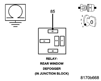
Turn the ignition off.
Remove the Rear Window Defogger Relay from the Junction Block.
Remove the Body Control Module from the Junction Block.
NOTE: Ensure the Junction Block connectors are reconnected at this time.
Measure the resistance between ground and the Rear Window Defogger Relay Control circuit in the relay connector of the Junction Block.
Is the resistance below 100.0 ohms?
Yes
- Replace the Junction Block.
- Perform BODY VERIFICATION TEST - VER 1. (Refer to 8 - ELECTRICAL/ELECTRONIC CONTROL MODULES - STANDARD PROCEDURE).
No
- Go To6
6. JUNCTION BLOCK - REAR WINDOW DEFOGGER RELAY CONTROL OPEN
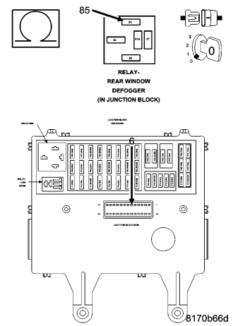
Turn the ignition off.
Remove the Rear Window Defogger Relay from the Junction Block.
Remove the Body Control Module from the Junction Block.
Measure the resistance of the Rear Window Defogger Relay Control circuit between the Relay connector and the Junction Block - BCM connector.
Is the resistance below 2.0 ohms?
Yes
- Go To7
No
- Replace the Junction Block.
- Perform BODY VERIFICATION TEST - VER 1. (Refer to 8 - ELECTRICAL/ELECTRONIC CONTROL MODULES - STANDARD PROCEDURE).
7. BODY CONTROL MODULE
If there are no possible causes remaining, view repair.
Repair
- Replace the Body Control Module.
- Perform BODY VERIFICATION TEST - VER 1. (Refer to 8 - ELECTRICAL/ELECTRONIC CONTROL MODULES - STANDARD PROCEDURE).
*REAR WINDOW DEFOGGER INOPERATIVE
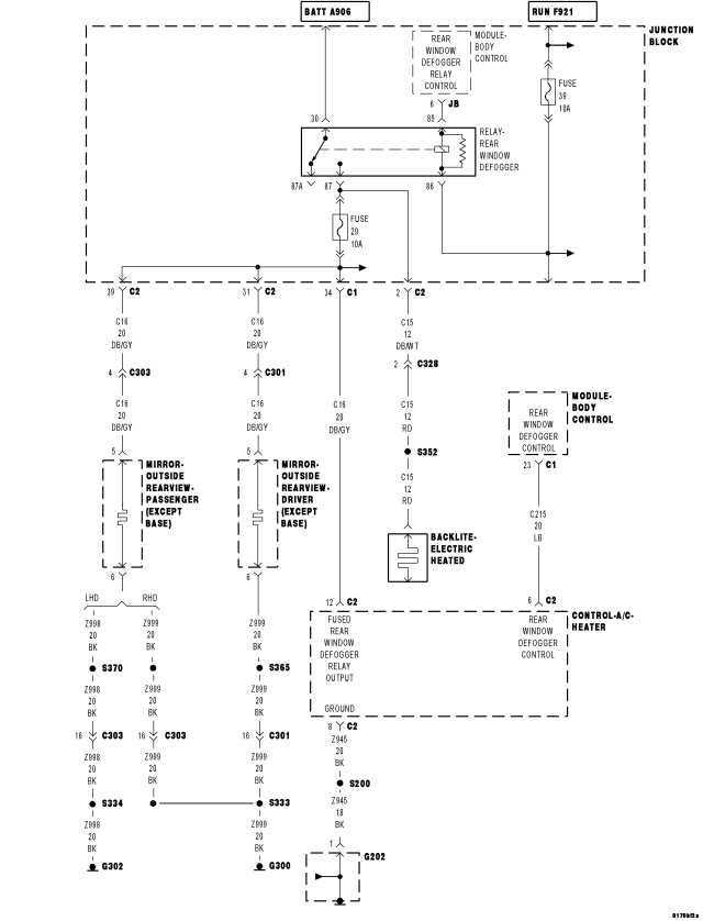
For a complete wiring diagram Refer to Section 8W.
| Possible Causes |
| JUNCTION BLOCK FUSE 29 |
| PDC FUSE 19 |
| REAR DEFOGGER RELAY DTC'S |
| REAR WINDOW DEFOGGER RELAY OUTPUT CIRCUIT OPEN |
| REAR WINDOW DEFOGGER RELAY |
| REAR WINDOW DEFOGGER GRID OPEN |
| FUSED B(+) CKT OPEN AT RELAY |
| A/C-HEATER CONTROL |
| OPEN GROUND CIRCUIT |
| FUSED REAR WINDOW DEFOGGER RELAY OUTPUT CIRCUIT OPEN |
| REAR WINDOW DEFOGGER CONTROL OPEN |
| BODY CONTROL MODULE |
| A/C-HEATER CONTROL LED |
Diagnostic Test
1. REAR DEFOGGER RELAY DTC'SWith the scan tool, read the Body Control Module DTC's.
Are there any Rear Defogger Relay DTC's present?
Yes
- Refer to the symptom list for problems related to Rear Defogger Relay DTC's.
- Perform BODY VERIFICATION TEST - VER 1. (Refer to 8 - ELECTRICAL/ELECTRONIC CONTROL MODULES - STANDARD PROCEDURE).
No
- Go To2
2. REAR DEFOGGER SWITCH OPERATION
Toggle the Rear Defogger switch and observe the indicator.
Does the indicator toggle on and off when the switch is pressed?
Yes
- Go To3
No
- Go To4
3. REAR DEFOGGER GRID OPEN
Turn the ignition on.
Turn the Rear Window Defogger on.
Measure the voltage between the Rear Window Defogger Relay Output circuit at the defogger grid on the rear window to ground.
Is the voltage above 12.0 volts?
Yes
- Repair the open in the Rear Window Defogger Grid or the Grid Ground circuit.
- Perform BODY VERIFICATION TEST - VER 1. (Refer to 8 - ELECTRICAL/ELECTRONIC CONTROL MODULES - STANDARD PROCEDURE).
No
- Repair the Rear Window Defogger Relay Output circuit for an open.
- Perform BODY VERIFICATION TEST - VER 1. (Refer to 8 - ELECTRICAL/ELECTRONIC CONTROL MODULES - STANDARD PROCEDURE).
4. SCAN TOOL ON/OFF STATE
With the scan tool, Rear Defogger Switch state.
Cycle the Rear Defogger On/Off button and observe the scan tool.
Did the scan tool display change?
Yes
- Go To5
No
- Go To10
5. PDC FUSE 19
Check the Power Distribution Center fuse 19.
Is the fuse open?
Yes
- Check for a short to ground and replace the PDC fuse.
- Perform BODY VERIFICATION TEST - VER 1. (Refer to 8 - ELECTRICAL/ELECTRONIC CONTROL MODULES - STANDARD PROCEDURE).
No
- Go To6
6. JUNCTION BLOCK FUSE 29
Check Junction Block fuse 29.
Is the fuse open?
Yes
- Check for a short to ground and replace the Junction Block fuse.
- Perform BODY VERIFICATION TEST - VER 1. (Refer to 8 - ELECTRICAL/ELECTRONIC CONTROL MODULES - STANDARD PROCEDURE).
No
- Go To7
7. FUSED B(+) CKT OPEN
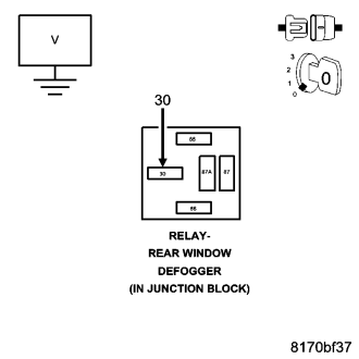
Remove the Rear Window Defogger Relay from the Junction Block.
Measure the voltage of the Fused B(+) circuit in the Rear Window Defogger Relay connector.
Is the voltage above 10.0 volts?
Yes
- Go To8
No
- Repair the open Fused B(+) circuit from PDC fuse 19.
- Perform BODY VERIFICATION TEST - VER 1. (Refer to 8 - ELECTRICAL/ELECTRONIC CONTROL MODULES - STANDARD PROCEDURE).
8. SUBSTITUTE RELAY
Remove the Rear Window Defogger Relay from the Junction Block.
Install a known good relay in the Rear Window Defogger Relay connector.
Turn the ignition on.
Toggle the Rear Window Defogger switch and observe the indicator.
Does the Rear Window Defogger indicator illuminate?
Yes
- Replace the original Rear Window Defogger Relay.
- Perform BODY VERIFICATION TEST - VER 1. (Refer to 8 - ELECTRICAL/ELECTRONIC CONTROL MODULES - STANDARD PROCEDURE).
No
- Go To9
9. A/C HEATER CONTROL LED
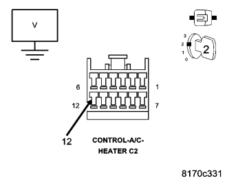
Gain access to the A/C Heater Control C2 connector.
Toggle the Rear Window Defogger switch in the next step.
While back probing, measure the voltage of the Fused Rear Window Defogger Relay Output circuit.
Is there any voltage present?
Yes
- Replace the A/C-Heater Control.
- Perform BODY VERIFICATION TEST - VER 1. (Refer to 8 - ELECTRICAL/ELECTRONIC CONTROL MODULES - STANDARD PROCEDURE).
No
- Repair the Fused Rear Window Defogger Relay Output circuit for an open.
- Perform BODY VERIFICATION TEST - VER 1. (Refer to 8 - ELECTRICAL/ELECTRONIC CONTROL MODULES - STANDARD PROCEDURE).
10. GROUND WIRE
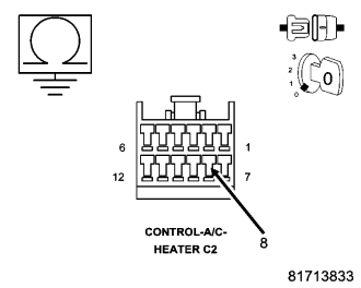
Turn the ignition off.
Disconnect the A/C-Heater Control C2 connector.
Turn of all interior lights.
Measure the resistance of the Ground circuit in the C2 connector.
Is the resistance below 5.0 ohms?
Yes
- Go To11
No
- Repair the ground circuit for an open.
- Perform BODY VERIFICATION TEST - VER 1. (Refer to 8 - ELECTRICAL/ELECTRONIC CONTROL MODULES - STANDARD PROCEDURE).
11. A/C HEATER CONTROL
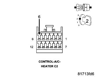
Turn the ignition off.
Disconnect the A/C-Heater Control C2 connector.
With the scan tool, read the Rear Defogger Switch state.
Connect a jumper wire between Rear Window Defogger Control and ground.
Did the scan tool display change?
Yes
- Replace the A/C-Heater Control.
- Perform BODY VERIFICATION TEST - VER 1. (Refer to 8 - ELECTRICAL/ELECTRONIC CONTROL MODULES - STANDARD PROCEDURE).
No
- Go To12
12. REAR WINDOW DEFOGGER CONTROL OPEN
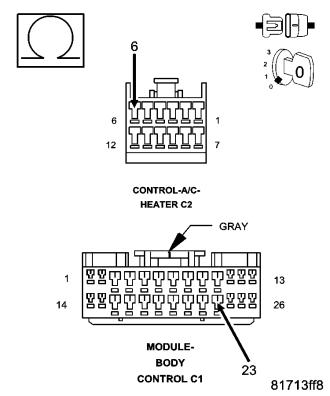
Turn the ignition off.
Disconnect the A/C-Heater Control C2 connector.
Disconnect the Body Control Module C1 connector.
Measure the resistance of the Rear Window Defogger Control circuit between the A/C- Heater Control C2 connector and the Body Control Module C1 connector.
Is the resistance below 5.0 ohms?
Yes
- Replace and program the Body Control Module in accordance with the Service Information.
- Perform BODY VERIFICATION TEST - VER 1. (Refer to 8 - ELECTRICAL/ELECTRONIC CONTROL MODULES - STANDARD PROCEDURE).
No
- Repair the Rear Window Defogger Control circuit for an open.
- Perform BODY VERIFICATION TEST - VER 1. (Refer to 8 - ELECTRICAL/ELECTRONIC CONTROL MODULES - STANDARD PROCEDURE).