*ALL GAUGES INOPERATIVE
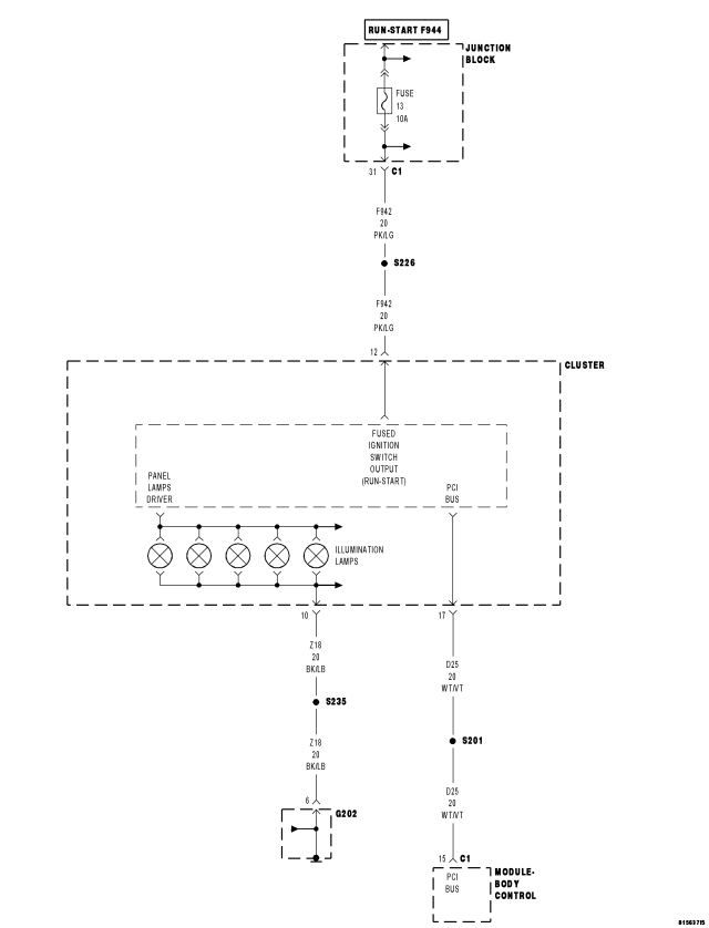
For a complete wiring diagram Refer to Section 8W.
| Possible Causes |
| NO RESPONSE - PCI BUS |
| NO RESPONSE - PCI BUS - POWERTRAIN CONTROL MODULE |
| NO RESPONSE - PCI BUS - INSTRUMENT CLUSTER |
| (F942) FUSED IGNITION SWITCH OUTPUT CIRCUIT SHORT TO GROUND |
| (Z18) INSTRUMENT CLUSTER GROUND CIRCUIT OPEN |
| (F942) FUSED IGNITION SWITCH OUTPUT CIRCUIT OPEN |
| INSTRUMENT CLUSTER |
Diagnostic Test
1. NO RESPONSE - PCI BUSTurn the ignition on.
With the scan tool, select System Monitors, then J1850 Module Scan.
Does the scan tool display: MIC PRESENT on the BUS?
Yes
- Go To2
No
- Refer to the COMMUNICATION category and perform the appropriate symptom.
- Perform BODY VERIFICATION TEST - VER 1. (Refer to 8 - ELECTRICAL/ELECTRONIC CONTROL MODULES - STANDARD PROCEDURE)
2. NO RESPONSE - PCI BUS - POWERTRAIN CONTROL MODULE
Turn the ignition on.
With the scan tool, select Body, MIC, SYSTEM TESTS, PCM Monitor.
Does the scan tool display: PCM INACTIVE on the BUS?
Yes
- Refer to the symptom list for problems related to *NO RESPONSE FROM THE POWERTRAIN CONTROL MODULE.
- Perform BODY VERIFICATION TEST - VER 1. (Refer to 8 - ELECTRICAL/ELECTRONIC CONTROL MODULES - STANDARD PROCEDURE)
No
- Go To3
3. NO RESPONSE - PCI BUS - INSTRUMENT CLUSTER
Turn the ignition on.
With the scan tool, select Body, MIC, MODULE DISPLAY.
Does the scan tool display: NO RESPONSE from MIC?
Yes
- Refer to the symptom list for problems related to *NO RESPONSE FROM THE INSTRUMENT CLUSTER.
- Perform BODY VERIFICATION TEST - VER 1. (Refer to 8 - ELECTRICAL/ELECTRONIC CONTROL MODULES - STANDARD PROCEDURE)
No
- Go To4
4. (F942) FUSED IGNITION SWITCH OUTPUT CIRCUIT SHORT TO GROUND
Turn the ignition off.
Inspect the #13 Fuse in the Junction Block.
If the fuse is open, replace with proper rated fuse.
Turn the ignition on for one minute.
Turn the ignition off.
Inspect the #13 Fuse in the Junction Block.
Is the fuse open?
Yes
- Repair the (F942) Fused Ignition Switch Output circuit for a short to ground.
- Perform BODY VERIFICATION TEST - VER 1. (Refer to 8 - ELECTRICAL/ELECTRONIC CONTROL MODULES - STANDARD PROCEDURE)
No
- Go To5
5. (F942) FUSED IGNITION SWITCH OUTPUT CIRCUIT OPEN
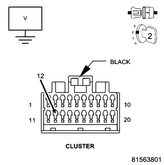
Turn the ignition off.
Disconnect the Instrument Cluster harness connector.
Turn the ignition on.
Measure the voltage between the (F942) Fused Ignition Switch Output circuit and ground.
Is the voltage above 10.5 volts?
Yes
- Go To6
No
- Repair the (F942) Fused Ignition Switch Output circuit for an open.
- Perform BODY VERIFICATION TEST - VER 1. (Refer to 8 - ELECTRICAL/ELECTRONIC CONTROL MODULES - STANDARD PROCEDURE)
6. (Z18) INSTRUMENT CLUSTER GROUND CIRCUIT OPEN
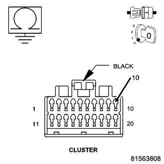
Turn the ignition off.
Disconnect the Instrument Cluster harness connector.
Measure the resistance between ground and the (Z18) Instrument Cluster Ground circuit.
Is the resistance below 5.0 ohms?
Yes
- Replace and configure the Instrument Cluster in accordance with the Service Information.
- Perform BODY VERIFICATION TEST - VER 1. (Refer to 8 - ELECTRICAL/ELECTRONIC CONTROL MODULES - STANDARD PROCEDURE)
No
- Repair (Z18) the Instrument Cluster Ground circuit for an open.
- Perform BODY VERIFICATION TEST - VER 1. (Refer to 8 - ELECTRICAL/ELECTRONIC CONTROL MODULES - STANDARD PROCEDURE)