DIAGNOSIS AND TESTING
- FRONT FOG RELAY CIRCUIT HIGH
- FRONT FOG RELAY CIRCUIT LOW
- HEADLAMP SWITCH INPUT CIRCUIT HIGH
- HEADLAMP SWITCH INPUT CIRCUIT LOW
- HIGH BEAM RELAY CIRCUIT HIGH
- *LOW BEAM HEADLAMPS INOPERATIVE
- LOW BEAM RELAY CIRCUIT HIGH
- LOW BEAM RELAY CIRCUIT LOW
- PARK LAMP RELAY CIRCUIT HIGH
- PARK LAMP RELAY CIRCUIT LOW
- REAR FOG RELAY CIRCUIT HIGH
- REAR FOG RELAY CIRCUIT LOW
FRONT FOG RELAY CIRCUIT HIGH
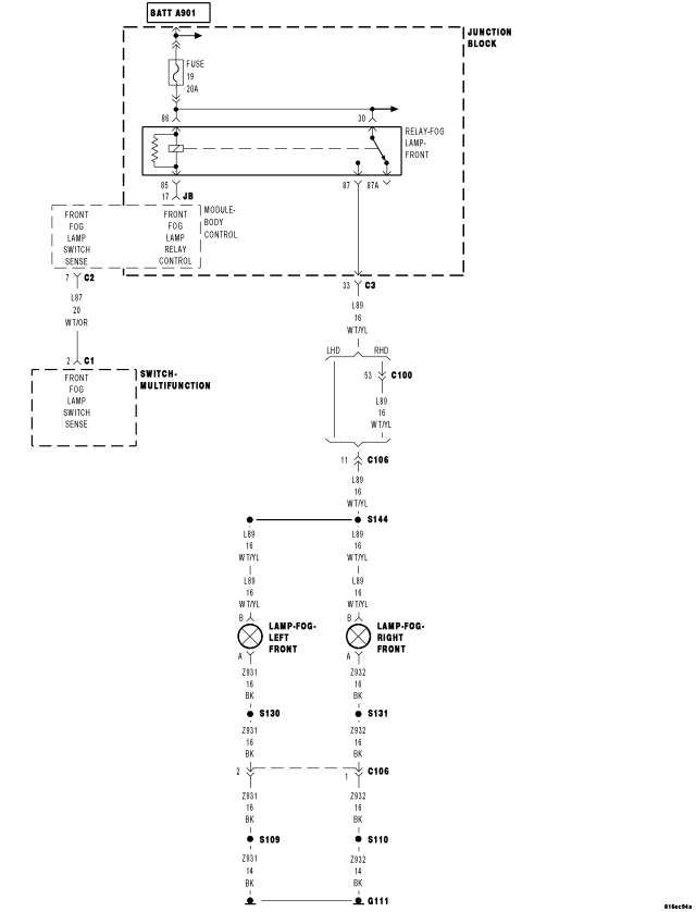
For a complete wiring diagram Refer to Section 8W
- When Monitored:
With the ignition on.
- Set Condition:
BCM detects battery on the Front Fog Relay when it is attempting to turn on the Front Fog Lamps for more than 5 seconds. The BCM learns that the Front Fog Options exists on a vehicle when it detects a ground on the Front Fog Switch Input circuit.
| Possible Causes |
| MISSING RELAY |
| OPEN FUSE |
| FOG LAMP RELAY |
| BODY CONTROL MODULE |
| FOG LAMP RELAY CONTROL CIRCUIT OPEN |
Diagnostic Test
1. INTERMITTENT CONDITIONTurn the ignition on.
With the Scan Tool, clear all BCM DTC's.
Turn the Fog Lamps on.
With the Scan Tool, read the DTC information.
Does the Scan Tool read: FRONT FOG RELAY CKT HIGH?
Yes
- Go To2
No
- The condition is not present at this time. Monitor scan tool parameters while wiggling the related wire harness. Refer to any Technical Service Bulletins that may apply. Visually inspect the related wiring harness and connector terminals.
- Perform BODY VERIFICATION TEST - VER 1.
2. MISSING RELAY
Turn the ignition off.
Check the Junction Block to make certain the Fog Lamp Relay is present.
Is the Fog Lamp Relay present?
Yes
- Go To3
No
- Replace the missing Fog Lamp Relay.
- Perform BODY VERIFICATION TEST - VER 1.
3. OPEN FUSE
Turn the ignition off.
Check Junction Block fuse 19.
Is the fuse open?
Yes
- Replace the open fuse.
- Perform BODY VERIFICATION TEST - VER 1.
No
- Go To4
4. FOG LAMP RELAY
Turn the ignition off.
Install a known good relay in place of the fog lamp relay.
Turn the Fog Lamps On.
Do the Fog Lamps operate normally?
Yes
- Replace the Fog Lamp Relay.
- Perform BODY VERIFICATION TEST - VER 1.
No
- Go To5
5. BODY CONTROL MODULE
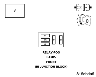
Turn the ignition off.
Remove the Fog Lamp Relay.
Measure the voltage of the Fused B+ circuit of the fog lamp relay.
Is the voltage above 10 volts?
Yes
- Replace the Body Control Module.
- Perform BODY VERIFICATION TEST - VER 1.
No
- Repair the Fog Lamp Relay Control Circuit for an open condition.
- Perform BODY VERIFICATION TEST - VER 1.
FRONT FOG RELAY CIRCUIT LOW
For a complete wiring diagram Refer to Section 8W
- When Monitored:
With the ignition on.
- Set Condition:
BCM detects a low (ground) on the Front Fog Relay even though it is not attempting to turn on the Front Fog Lamps for more than 5 seconds.
| Possible Causes |
| FRONT FOG RELAY SHORT TO GROUND |
| FRONT FOG RELAY |
| BODY CONTROL MODULE |
Diagnostic Test
1. INTERMITTENT CONDITIONTurn the ignition on.
With the Scan Tool, clear all BCM DTC's.
Turn the Fog Lamps on.
With the Scan Tool, read the DTC information.
Does the Scan Tool read: FRONT FOG RELAY CKT LOW?
Yes
- Go To2
No
- The condition is not present at this time. Monitor Scan Tool parameters while wiggling the related wire harness. Refer to any Technical Service Bulletins that may apply. Visually inspect the related wiring harness and connector terminals.
- Perform BODY VERIFICATION TEST - VER 1.
2. FRONT FOG RELAY SHORT TO GROUND
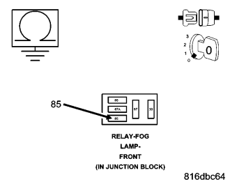
Turn the ignition off.
Disconnect the Front Fog Relay.
Measure the resistance between ground and the Front Fog Relay Control circuit.
Is the resistance below 5.0 ohms?
Yes
- Repair the Front Fog Relay Control circuit for a short to ground.
- Perform BODY VERIFICATION TEST - VER 1.
No
- Go To3
3. FRONT FOG RELAY
Turn the ignition off.
Disconnect the Front Fog Relay harness connector.
Measure the voltage of the Front Fog Relay harness connector coil side feed circuit to ground.
Is the voltage above 10.0 volts?
Yes
- Replace the Fog Lamp Relay.
- Perform BODY VERIFICATION TEST - VER 1.
No
- Replace the Body Control Module.
- Perform BODY VERIFICATION TEST - VER 1.
HEADLAMP SWITCH INPUT CIRCUIT HIGH
For a complete wiring diagram Refer to Section 8W
- When Monitored:
Ignition on.
- Set Condition:
The BCM detects a voltage greater than 4.75 V on the Headlamp Switch Input for more than 5 seconds.
| Possible Causes |
| HEADLAMP SWITCH OPEN |
| HEADLAMP SWITCH MUX CIRCUIT OPEN |
| HEADLAMP SWITCH RETURN CIRCUIT OPEN |
| BODY CONTROL MODULE |
Diagnostic Test
1. INTERMITTENT CONDITIONTurn the ignition on.
With the Scan Tool, erase all BCM DTC's.
Turn the headlamps to the ON position.
With the Scan Tool, read DTCs.
Does the Scan Tool display: HEADLAMP SWITCH INPUT CKT HIGH?
Yes
- Go To2
No
- The condition is not present at this time. Monitor Scan Tool parameters while wiggling the related wire harness. Refer to any Technical Service Bulletins that may apply. Visually inspect the related wiring harness and connector terminals.
- Perform BODY VERIFICATION TEST - VER 1.
2. HEADLAMP SWITCH OPEN
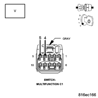
Turn the ignition off.
Disconnect the Multifunction Switch harness connector.
Connect a jumper wire between the Headlamp Switch MUX circuit and the Headlamp Switch Return circuit in the Multifunction Switch harness connector.
Turn the ignition on.
With the Scan Tool, select Body, Body Controller and read: Headlamp Switch volts.
Does the Scan Tool display Headlamp Switch voltage below 0.5 volts?
Yes
- Replace the Headlamp Switch.
- Perform BODY VERIFICATION TEST - VER 1.
No
- Go To3
3. HEADLAMP SWITCH MUX CIRCUIT OPEN
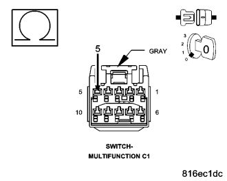
Turn the ignition off.
Disconnect the Body Control Module harness connector.
Disconnect the Multifunction Switch harness connector.
Measure resistance of the Headlamp Switch MUX circuit from the Body Control Module connector to the Multifunction Switch harness connector.
Is the resistance above 5.0 ohms?
Yes
- Repair the Headlamp Switch MUX circuit for an open condition.
- Perform BODY VERIFICATION TEST - VER 1.
No
- Go To4
4. HEADLAMP SWITCH RETURN CIRCUIT OPEN
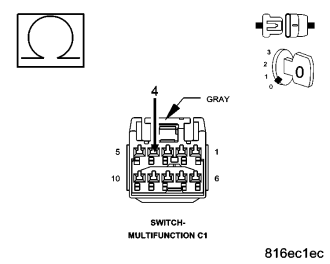
Turn the ignition off.
Disconnect the Body Control Module harness connector.
Disconnect the Multifunction Switch C1 harness connector.
Measure resistance of the Headlamp Switch Return circuit from the Body Control Module connector to the Multifunction Switch harness connector.
Is the resistance above 5.0 ohms?
Yes
- Repair the Headlamp Switch Return circuit for an open condition.
- Perform BODY VERIFICATION TEST - VER 1.
No
- Replace the Body Control Module.
- Perform BODY VERIFICATION TEST - VER 1.
HEADLAMP SWITCH INPUT CIRCUIT LOW
For a complete wiring diagram Refer to Section 8W
- When Monitored:
Ignition on.
- Set Condition:
BCM detects a voltage less than 0.25 volts on the Headlamp Switch Input for more than 5 seconds.
| Possible Causes |
| HEADLAMP SWITCH SHORTED |
| HEADLAMP SWITCH MUX CIRCUIT SHORT TO RETURN CIRCUIT |
| HEADLAMP SWITCH MUX CIRCUIT SHORT TO GROUND |
| HEADLAMP SWITCH RETURN CIRCUIT SHORT TO GROUND |
| BODY CONTROL MODULE |
Diagnostic Test
1. INTERMITTENT CONDITIONTurn the ignition on.
With the Scan Tool, clear all BCM DTC's.
Turn the headlamps to the ON position.
With the Scan Tool, read DTCs.
Does the Scan Tool display: HEADLAMP SWITCH INPUT CKT LOW?
Yes
- Go To2
No
- The condition is not present at this time. Monitor Scan Tool parameters while wiggling the related wire harness. Refer to any Technical Service Bulletins that may apply. Visually inspect the related wiring harness and connector terminals.
- Perform BODY VERIFICATION TEST - VER 1.
2. HEADLAMP SWITCH SHORTED
Turn the ignition off.
Disconnect the Multifunction Switch harness connector.
Turn the ignition on.
With the Scan Tool, select Body, Body Control Module and read: Headlamp Switch voltage.
Does the Scan Tool display Headlamp Switch voltage above 4.8 volts?
Yes
- Replace the Multifunction Switch.
- Perform BODY VERIFICATION TEST - VER 1.
No
- Go To3
3. HEADLAMP SWITCH MUX CIRCUIT SHORT TO MUX RETURN CIRCUIT
Turn the ignition off.
Disconnect the Body Control Module harness connector.
Disconnect the Multifunction Switch harness connector.
Measure resistance between the Headlamp Switch Return circuit and the Headlamp Switch MUX circuit.
Is the resistance below 5.0 ohms?
Yes
- Repair the Headlamp Switch MUX circuit for a short to the Headlamp Switch Return circuit.
- Perform BODY VERIFICATION TEST - VER 1.
No
- Go To4
4. HEADLAMP SWITCH MUX CIRCUIT SHORT TO GROUND
Turn the ignition off.
Disconnect the Body Control Module harness connector.
Disconnect the Multifunction Switch harness connector.
Measure resistance between ground and the Headlamp Switch MUX circuit.
Is the resistance above 5.0 ohms?
Yes
- Repair the Headlamp Switch MUX Circuit for a short to ground condition.
- Perform BODY VERIFICATION TEST - VER 1.
No
- Go To5
5. HEADLAMP SWITCH RETURN CIRCUIT SHORT TO GROUND
Turn the ignition off.
Disconnect the Body Control Module harness connector.
Disconnect the Multifunction Switch harness connector.
Measure resistance between ground and the Headlamp Switch Return circuit.
Is the resistance below 5.0 ohms?
Yes
- Repair the Headlamp Switch Return Circuit for a short to ground condition.
- Perform BODY VERIFICATION TEST - VER 1.
No
- Replace the Body Control Module.
- Perform BODY VERIFICATION TEST - VER 1.
HIGH BEAM RELAY CIRCUIT HIGH
For a complete wiring diagram Refer to Section 8W
- When Monitored:
With ignition on.
- Set Condition:
BCM detects battery on the High Beam Relay when it is attempting to turn on the High Beams for more than 5 seconds.
| Possible Causes |
| MISSING RELAY |
| OPEN FUSE |
| HIGH BEAM RELAY |
| MULTIFUNCTION SWITCH |
| HIGH BEAM SWITCH SENSE CIRCUIT OPEN |
Diagnostic Test
1. INTERMITTENT CONDITIONTurn the ignition on.
With the Scan Tool, clear all BCM DTC's.
Turn the High Beams on.
With the Scan Tool, read the DTC information.
Does the Scan Tool read: HIGH BEAM RELAY CIRCUIT HIGH?
Yes
- Go To2
No
- The condition is not present at this time. Monitor scan tool parameters while wiggling the related wire harness. Refer to any Technical Service Bulletins that may apply. Visually inspect the related wiring harness and connector terminals.
- Perform BODY VERIFICATION TEST - VER 1.
2. MISSING RELAY
Turn the ignition off.
Check the Junction Block to make certain the High Beam Relay is present.
Is the High Beam Relay present?
Yes
- Go To3
No
- Replace the missing High Beam Relay.
- Perform BODY VERIFICATION TEST - VER 1.
3. OPEN FUSE
Turn the ignition off.
Check the Junction Block High Beam fuses 26 and 27.
Are any of the fuses open?
Yes
- Replace the open fuse.
- Perform BODY VERIFICATION TEST - VER 1.
No
- Go To4
4. HIGH BEAM RELAY
Turn the ignition off.
Install a known good relay in place of the High Beam Relay.
Turn the High Beams On.
Do the High Beams operate normally?
Yes
- Replace the High Beam Relay.
- Perform BODY VERIFICATION TEST - VER 1.
No
- Go To5
5. MULTIFUNCTION SWITCH
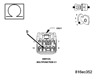
Turn the ignition off.
Disconnect the Multifunction Switch harness connector C1.
Disconnect the BCM C2 connector.
Measure the resistance of the High Beam Switch Sense circuit.
Is the resistance below 5.0 ohms?
Yes
- Replace the Multifunction Switch.
- Perform BODY VERIFICATION TEST - VER 1.
No
- Repair the High Beam Switch Sense circuit for an open condition.
- Perform BODY VERIFICATION TEST - VER 1.
*LOW BEAM HEADLAMPS INOPERATIVE
For a complete wiring diagram Refer to Section 8W
- When Monitored:
Possible Causes
- Set Condition:
Possible Causes
| Possible Causes |
| LOW BEAM RELAY |
| OPEN FUSED B+ CIRCUIT |
| LOW BEAM RELAY CONTROL CIRCUIT |
| LOW BEAM RELAY |
| BODY CONTROL MODULE |
Diagnostic Test
1. INTERMITTENT CONDITIONTurn the Low Beams on.
Do the Low Beam Headlamps operate properly?
Yes
- The condition is not present at this time. Monitor Scan Tool parameters while wiggling the related wire harness. Refer to any Technical Service Bulletins that may apply. Visually inspect the related wiring harness and connector terminals.
- Perform BODY VERIFICATION TEST - VER 1.
No
- Go To2
2. LOW BEAM RELAY
Remove the Low Beam Relay from the Junction Block.
Install a known good relay in place of the Low Beam Relay.
With the Scan Tool, actuate the Low Beam Relay.
Do the Headlamps flash while actuating the Low Beam Relay?
Yes
- Replace the Low Beam Relay.
- Perform BODY VERIFICATION TEST - VER 1.
No
- Go To3
3. OPEN FUSED B(+) CIRCUIT
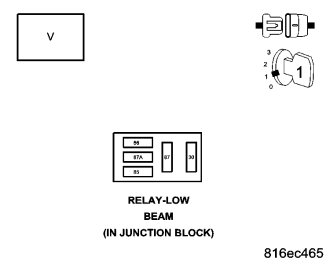
Remove the Low Beam Relay from the Junction Block.
Measure the voltage of the Fused B(+) circuit at the Low Beam Relay connector.
Is the voltage above 10.0 volts?
Yes
- Go To4
No
- Repair the open fused B+ circuit.
- Perform BODY VERIFICATION TEST - VER 1.
4. LOW BEAM RELAY CONTROL CIRCUIT
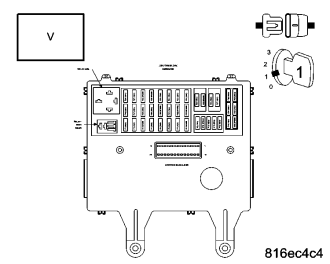
Remove the BCM from the junction block.
Connect a jumper wire between the Fused B(+) circuit and the Low Beam Relay Control circuit at the Low Beam Relay connector.
Measure the voltage of the Low Beam Relay Control circuit to the BCM Junction Block connector.
Is the voltage above 10.0 volts?
Yes
- Go To5
No
- Repair the Low Beam Relay Control circuit for an open condition.
- Perform BODY VERIFICATION TEST - VER 1.
5. LOW BEAM HEADLAMP RELAY
Disconnect the jumper wire.
Reinstall the Low Beam Relay in the Junction Block.
Remove the BCM from the junction block.
Measure the voltage of the Low Beam Relay Control circuit to the BCM internal connector.
Is the voltage above 10.0 volts?
Yes
- Replace the Body Control Module.
- Perform BODY VERIFICATION TEST - VER 1.
No
- Replace the Low Beam Relay.
- Perform BODY VERIFICATION TEST - VER 1.
LOW BEAM RELAY CIRCUIT HIGH
For a complete wiring diagram Refer to Section 8W
- When Monitored:
With ignition on
- Set Condition:
BCM detects battery on the Low Beam Relay when it is attempting to turn on the Low Beams for more than 5 seconds.
| Possible Causes |
| MISSING RELAY |
| OPEN FUSE |
| LOW BEAM RELAY |
| BODY CONTROL MODULE |
| FUSED LOW BEAM RELAY OUTPUT CIRCUIT OPEN |
Diagnostic Test
1. INTERMITTENT CONDITIONTurn the ignition on.
With the scan tool, clear all BCM DTC's.
Turn the Low Beams on.
With the scan tool, read the DTC information.
Does the scan tool read: LOW BEAM RELAY CIRCUIT HIGH?
Yes
- Go To2
No
- The condition is not present at this time. Monitor scan tool parameters while wiggling the related wire harness. Refer to any Technical Service Bulletins that may apply. Visually inspect the related wiring harness and connector terminals.
- Perform BODY VERIFICATION TEST - VER 1.
2. MISSING RELAY
Turn the ignition off.
Check the Junction Block to make certain the Low Beam Relay is present.
Is the Low Beam Relay present?
Yes
- Go To3
No
- Replace the missing Low Beam Relay.
- Perform BODY VERIFICATION TEST - VER 1.
3. OPEN FUSE
Turn the ignition off.
Check the Junction Block Low Beam fuses 4 and 5.
Are any of the fuses open?
Yes
- Replace the open fuse.
- Perform BODY VERIFICATION TEST - VER 1.
No
- Go To4
4. LOW BEAM RELAY
Turn the ignition off.
Install a known good relay in place of the Low Beam Relay.
Turn the Low Beams On.
Do the Low Beams operate normally?
Yes
- Replace the Low Beam Relay.
- Perform BODY VERIFICATION TEST - VER 1.
No
- Go To5
5. BODY CONTROL MODULE
Turn the ignition off
Remove the Low Beam Relay.
Measure the voltage of the Fused B+ circuit of the Low Beam Relay.
Is the voltage above 10 volts?
Yes
- Replace the Body Control Module.
- Perform BODY VERIFICATION TEST - VER 1.
No
- Repair the Fused Low Beam Relay Output circuit for an open condition.
- Perform BODY VERIFICATION TEST - VER 1.
LOW BEAM RELAY CIRCUIT LOW
For a complete wiring diagram Refer to Section 8W
- When Monitored:
With ignition on.
- Set Condition:
BCM detects a low (ground) on the Low Beam Relay even though it is not attempting to turn on the Low Beams for more than 5 seconds.
| Possible Causes |
| LOW BEAM RELAY SHORT TO GROUND |
| LOW BEAM RELAY |
| BODY CONTROL MODULE |
Diagnostic Test
1. INTERMITTENT CONDITIONTurn the ignition on.
With the scan tool, clear all BCM DTC's.
Turn the Low Beams on.
With the scan tool, read the DTC information.
Does the scan tool read: LOW BEAM RELAY CKT LOW?
Yes
- Go To2
No
- The condition is not present at this time. Monitor DRBIII parameters while wiggling the related wire harness. Refer to any Technical Service Bulletins that may apply. Visually inspect the related wiring harness and connector terminals.
- Perform BODY VERIFICATION TEST - VER 1.
2. LOW BEAM RELAY SHORT TO GROUND
Turn the ignition off.
Disconnect the Low Beam Relay.
Measure the resistance between ground and the Low Beam Relay Control circuit.
Is the resistance below 5.0 ohms?
Yes
- Repair the Low Beam Relay Control circuit for a short to ground.
- Perform BODY VERIFICATION TEST - VER 1.
No
- Go To3
3. LOW BEAM RELAY
Turn the ignition off.
Disconnect the Low Beam Relay harness connector.
Measure the voltage of the Low Beam Relay harness connector coil side feed circuit to ground.
Is the voltage above 10.0 volts?
Yes
- Replace the Low Beam Relay.
- Perform BODY VERIFICATION TEST - VER 1.
No
- Replace the Body Control Module.
- Perform BODY VERIFICATION TEST - VER 1.
PARK LAMP RELAY CIRCUIT HIGH
For a complete wiring diagram Refer to Section 8W
- When Monitored:
With the ignition on.
- Set Condition:
BCM detects battery on the Park Lamp Relay when it is attempting to turn on the Park Lamps for more than 5 seconds.
| Possible Causes |
| MISSING RELAY |
| OPEN FUSE |
| PARK LAMP RELAY |
| BODY CONTROL MODULE |
| FUSED PARK LAMP RELAY OUTPUT CIRCUIT OPEN |
Diagnostic Test
1. INTERMITTENT CONDITIONTurn the ignition on.
With the scan tool, clear all BCM DTC's.
Turn the Park Lamps on.
With the scan tool, read the DTC information.
Does the scan tool read: PARK LAMP RELAY CKT HIGH?
Yes
- Go To2
No
- The condition is not present at this time. Monitor scan tool parameters while wiggling the related wire harness. Refer to any Technical Service Bulletins that may apply. Visually inspect the related wiring harness and connector terminals.
- Perform BODY VERIFICATION TEST - VER 1.
2. MISSING RELAY
Turn the ignition off.
Check the Junction Block to make certain the Park Lamp Relay is present.
Is the Park Lamp Relay present?
Yes
- Go To3
No
- Replace the missing Park Lamp Relay.
- Perform BODY VERIFICATION TEST - VER 1.
3. OPEN FUSE
Turn the ignition off.
Check the Junction Block Park Lamp fuses 23 and 9.
Are any of the fuses open?
Yes
- Replace the open fuse.
- Perform BODY VERIFICATION TEST - VER 1.
No
- Go To4
4. PARK LAMP RELAY
Turn the ignition off.
Install a known good relay in place of the Park Lamp Relay.
Turn the Park Lamps On.
Do the Park Lamps operate normally?
Yes
- Replace the Park Lamp Relay.
- Perform BODY VERIFICATION TEST - VER 1.
No
- Go To5
5. BODY CONTROL MODULE
Turn the ignition off.
Remove the Park Lamp Relay.
Measure the voltage of the Fused B+ circuit of the Park Lamp Relay.
Is the voltage above 10 volts?
Yes
- Replace the Body Control Module.
- Perform BODY VERIFICATION TEST - VER 1.
No
- Repair the Fused Park Lamp Relay Output circuit for an open condition.
- Perform BODY VERIFICATION TEST - VER 1.
PARK LAMP RELAY CIRCUIT LOW
For a complete wiring diagram Refer to Section 8W
- When Monitored:
With ignition on.
- Set Condition:
BCM detects a low (ground) on the Park Lamp Relay even though it is not attempting to turn on the Park Lamps for more than 5 seconds.
| Possible Causes |
| PARK LAMP RELAY SHORT TO GROUND |
| PARK LAMP RELAY |
| BODY CONTROL MODULE |
Diagnostic Test
1. INTERMITTENT CONDITIONTurn the ignition on.
With the scan tool, clear all BCM DTC's.
Turn the Park Lamps on.
With the scan tool, read the DTC information.
Does the scan tool read: PARK LAMP RELAY CKT LOW?
Yes
- Go To2
No
- The condition is not present at this time. Monitor scan tool parameters while wiggling the related wire harness. Refer to any Technical Service Bulletins that may apply. Visually inspect the related wiring harness and connector terminals.
- Perform BODY VERIFICATION TEST - VER 1.
2. PARK LAMP RELAY SHORT TO GROUND
Turn the ignition off.
Disconnect the Park Lamp Relay.
Measure the resistance between ground and the Park Lamp Relay Control circuit.
Is the resistance below 5.0 ohms?
Yes
- Repair the Park lamp Relay Control circuit for a short to ground.
- Perform BODY VERIFICATION TEST - VER 1.
No
- Go To3
3. PARK LAMP RELAY
Turn the ignition off.
Disconnect the Park Lamp Relay harness connector.
Measure the voltage of the Park Lamp Relay harness connector coil side feed circuit to ground.
Is the voltage above 10.0 volts?
Yes
- Replace the Park Lamp Relay.
- Perform BODY VERIFICATION TEST - VER 1.
No
- Replace the Body Control Module.
- Perform BODY VERIFICATION TEST - VER 1.
REAR FOG RELAY CIRCUIT HIGH
For a complete wiring diagram Refer to Section 8W
- When Monitored:
With the ignition on.
- Set Condition:
BCM detects battery on the Rear Fog Relay when it is attempting to turn on the Front Fog Lamps for more than 5 seconds. The BCM is programmed per Country Code whether or not a vehicle is equipped with a Rear Fog Relay.
| Possible Causes |
| MISSING RELAY |
| OPEN FUSE |
| FOG LAMP RELAY |
| BODY CONTROL MODULE |
| FOG LAMP RELAY CONTROL CIRCUIT OPEN |
Diagnostic Test
1. INTERMITTENT CONDITIONTurn the ignition on.
With the scan tool, clear all BCM DTC's.
Turn the Fog Lamps on.
With the scan tool, read the DTC information.
Does the scan tool read: REAR FOG RELAY CIRCUIT HIGH?
Yes
- Go To2
No
- The condition is not present at this time. Monitor scan tool parameters while wiggling the related wire harness. Refer to any Technical Service Bulletins that may apply. Visually inspect the related wiring harness and connector terminals.
- Perform BODY VERIFICATION TEST - VER 1.
2. MISSING RELAY
Turn the ignition off.
Check the Junction Block to make certain the Rear Fog Lamp Relay is present.
Is the Rear Fog Lamp Relay present?
Yes
- Go To3
No
- Replace the missing Fog Lamp Relay.
- Perform BODY VERIFICATION TEST - VER 1.
3. OPEN FUSE
Turn the ignition off.
Check Junction Block fuse 2.
Is the fuse open?
Yes
- Replace the open fuse.
- Perform BODY VERIFICATION TEST - VER 1.
No
- Go To4
4. FOG LAMP RELAY
Turn the ignition off.
Install a known good relay in place of the Rear Fog Lamp Relay.
Turn the Fog Lamps On.
Do the Rear Fog Lamps operate normally?
Yes
- Replace the Fog Lamp Relay.
- Perform BODY VERIFICATION TEST - VER 1.
No
- Go To5
5. BODY CONTROL MODULE
Turn the ignition off.
Remove the Fog Lamp Relay.
Measure the voltage of the Fused B+ circuit of the Fog Lamp Relay.
Is the voltage above 10 volts?
Yes
- Replace the Body Control Module.
- Perform BODY VERIFICATION TEST - VER 1.
No
- Repair the Fog Lamp Relay Control Circuit for an open condition.
- Perform BODY VERIFICATION TEST - VER 1.
REAR FOG RELAY CIRCUIT LOW
For a complete wiring diagram Refer to Section 8W
- When Monitored:
With the ignition on.
- Set Condition:
BCM detects a low (ground) on the Fog Relay even though it is not attempting to turn on the Rear Fog Lamps for more than 5 seconds.
| Possible Causes |
| LOW BEAM RELAY |
| OPEN FUSED B+ CIRCUIT |
| LOW BEAM RELAY CONTROL CIRCUIT |
| LOW BEAM RELAY |
| BODY CONTROL MODULE |
Diagnostic Test
1. INTERMITTENT CONDITIONTurn the ignition on.
With the scan tool, clear all BCM DTC's.
Turn the Fog Lamps on.
With the scan tool, read the DTC information.
Does the scan tool read: Rear Fog Relay Circuit Low?
Yes
- Go To2
No
- The condition is not present at this time. Monitor scan tool parameters while wiggling the related wire harness. Refer to any Technical Service Bulletins that may apply. Visually inspect the related wiring harness and connector terminals.
- Perform BODY VERIFICATION TEST - VER 1.
2. REAR FOG RELAY SHORT TO GROUND
Turn the ignition off.
Disconnect the Rear Fog Relay.
Measure the resistance between ground and the Rear Fog Relay Control circuit.
Is the resistance below 5.0 ohms?
Yes
- Repair the Rear Fog Relay Control circuit for a short to ground.
- Perform BODY VERIFICATION TEST - VER 1.
No
- Go To3
3. REAR FOG RELAY
Turn the ignition off.
Disconnect the Rear Fog Relay harness connector from the Junction Block.
Measure the voltage of the Rear Fog Relay harness connector coil side feed circuit to ground.
Is the voltage above 10.0 volts?
Yes
- Replace the Rear Fog Lamp Relay.
- Perform BODY VERIFICATION TEST - VER 1.
No
- Replace the Body Control Module.
- Perform BODY VERIFICATION TEST - VER 1.