LAMP BAR SWITCH
DESCRIPTION
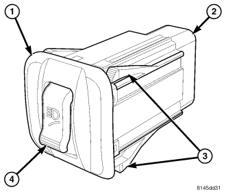
The light bar lamp switch (1) is used only on vehicles equipped with the optional light bar and off road lamps. The light bar lamp switch is mounted in the driver side outboard trim bezel on the instrument panel. Only the switch bezel and rocker (4) are visible on the outer surface of the instrument panel trim bezel. The black plastic switch rocker is marked with an icon that is similar in appearance to the International Control and Display Symbol icon for High Beam, but has an additional curved line beneath it to represent the forward roofline of the vehicle. The icon is illuminated when the exterior lighting is turned ON.
The black, molded plastic switch housing encloses the momentary switch rocker mechanism and the switch circuitry including an integral relay and active electronic elements. A connector receptacle (2) is integral to the back of the switch housing, while a two integral latch features (3) on the top and bottom of the housing secure the switch in the instrument panel trim bezel. The switch is connected to the vehicle electrical system through a dedicated take out and connector of the instrument panel wire harness.
The light bar lamp switch cannot be adjusted or repaired and, if ineffective or damaged, the unit must be replaced.
OPERATION
In vehicles manufactured for North American markets, the light bar lamp switch operates on battery voltage received on a fused ignition switch output (run-start) circuit from a fuse in the Junction Block (JB) whenever the ignition switch is in the ON or START positions. In vehicles manufactured for export markets, the switch operates on battery voltage received from the park lamp relay in the JB on a park lamp relay output circuit whenever the park lamp relay is energized. The switch receives a path to ground through a splice block in the instrument panel wire harness secured by a nut to a ground stud on the driver side instrument panel end bracket near the JB.
The switch also receives battery voltage on a fused B(+) circuit that the relay within the switch controls to energize and de-energize the light bar lamps through an output on the lightbar switch output circuit. A panel lamps driver input is used to illuminate the icon on the switch rocker when the exterior lighting is turned ON. In certain markets where it is required, the switch also receives a logic input on a low beam driver circuit, which allows the switch to disallow the light bar lamps from operating unless the park lamps are turned ON and the low beam headlamps are turned OFF.
Another output from the switch is a voltage signal that it provides to the Body Control Module (BCM) on a lightbar switch sense circuit. The BCM sends electronic messages over the Programmable Communications Interface (PCI) data bus to the instrument cluster based upon this input to control illumination of the light bar lamp indicator or the high beam indicator as required by the market for which the vehicle was manufactured.
Because of active electronic elements within the light bar lamp switch, it cannot be tested using conventional diagnostic tools or procedures. If a problem is noted with the light bar lamp system operation, test and confirm the input and output circuits of the switch are in good condition before replacing the switch.
REMOVAL
WARNING: To avoid personal injury or death, on vehicles equipped with airbags, disable the supplemental restraint system before attempting any steering wheel, steering column, airbag, occupant classification system, seat belt tensioner, impact sensor, or instrument panel component diagnosis or service. Disconnect and isolate the battery negative (ground) cable, then wait two minutes for the system capacitor to discharge before performing further diagnosis or service. This is the only sure way to disable the supplemental restraint system. Failure to take the proper precautions could result in accidental airbag deployment.
NOTE: A light bar lamp switch is used only on vehicles equipped with the optional light bar and auxiliary off-road lamps.
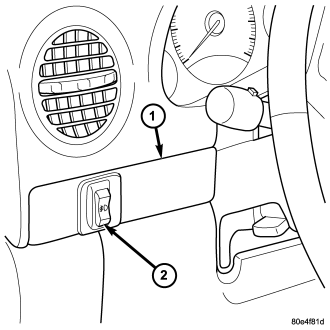
1. Disconnect negative battery cable.
2. Remove the driver side outboard bezel (1) from the instrument panel. (Refer to 23 - BODY/INSTRUMENT PANEL/INSTRUMENT PANEL DRIVER SIDE BEZEL - REMOVAL).
3. Disconnect the instrument panel wire harness connector from the light bar lamp switch (2) connector receptacle.
4. From the back of the trim bezel, depress the two lower latch features on the switch housing and rock the bottom of the switch out through the face of the bezel.
5. From the back of the trim bezel, depress the two upper latch features on the switch housing and push the switch out through the face of the bezel.
INSTALLATION
WARNING: To avoid personal injury or death, on vehicles equipped with airbags, disable the supplemental restraint system before attempting any steering wheel, steering column, airbag, occupant classification system, seat belt tensioner, impact sensor, or instrument panel component diagnosis or service. Disconnect and isolate the battery negative (ground) cable, then wait two minutes for the system capacitor to discharge before performing further diagnosis or service. This is the only sure way to disable the supplemental restraint system. Failure to take the proper precautions could result in accidental airbag deployment.
NOTE: A light bar lamp switch is used only on vehicles equipped with the optional light bar and auxiliary off-road lamps.
1. From the face of the driver side outboard bezel (1), align the light bar lamp switch housing (2) to the mounting hole in the bezel.
2. Push the switch into the mounting hole until it is fully seated and each of the latch features is fully engaged.
3. Reconnect the instrument panel wire harness connector to the switch connector receptacle.
4. Reinstall the trim bezel and switch unit onto the instrument panel. (Refer to 23 - BODY/INSTRUMENT PANEL/INSTRUMENT PANEL DRIVER SIDE BEZEL - INSTALLATION).
5. Reconnect the battery negative cable.