TRAILER TOW RELAY
DESCRIPTION
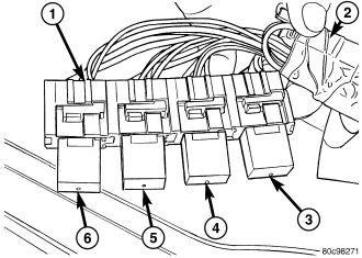
Vehicles equipped with an optional factory-installed trailer towing package have four trailer tow relays. The trailer tow relays are conventional International Standards Organization (ISO) micro relays. Relays conforming to the ISO specifications have common physical dimensions, current capacities, terminal patterns, and terminal functions. Each relay is contained within a small, rectangular, molded plastic housing and is connected to all of the required inputs and outputs through five integral male spade-type terminals that extend from the relay base plate.
The trailer tow relays include one each for brake lamps (5), right turn lamps (4), left turn lamps (3) and a fused ignition switch output (run) circuit (6) which are provided for the trailer through the rear body wiring (2) and connectors. The relays are located in a connector bank (1) above the right rear wheelhouse and behind the quarter trim panel. The connector bank and relays are wrapped within a foam rubber isolator envelope for sound deadening and anti-rattle protection. Refer to Trailer Tow in the wiring information for specific relay cavity assignment information.
A trailer tow relay cannot be adjusted or repaired and, if ineffective or damaged, the unit must be replaced.
OPERATION
The trailer tow relays are electromechanical switches that each use a low current input from the circuit that they isolate to control a high current output to the trailer brake and turn signal lamps, and a trailer accessory circuit. Within each relay are an electromagnetic coil, a movable contact and two fixed contact points. A resistor is connected in parallel with the coil, and helps to dissipate voltage spikes and electromagnetic interference that can be generated as the field of the relay coil collapses.
The movable common supply contact point is held against the fixed normally closed contact point by spring pressure. When the relay coil is energized, an electromagnetic field is produced by the coil windings. This field draws the movable contact away from the normally closed contact, and holds it against the normally open contact. When the relay coil is de-energized, spring pressure returns the movable contact back against the normally closed contact.
The inputs and outputs of the trailer tow relays include:
- Common Supply Terminal (30) - The common feed terminal is connected to the circuit connected to the normally open terminal (87) when the relay is energized, or to the circuit connected to the normally closed terminal (87A) when the relay is de-energized.
- Coil Ground Terminal (85) - The coil ground terminal is connected to a ground circuit at all times.
- Coil Battery Terminal (86) - The coil battery terminal is connected to the circuit that controls the relay output. When battery voltage is applied to this terminal, the relay is energized.
- Normally Open Terminal (87) - The normally open terminal is connected to the circuit connected to the common supply terminal (30) whenever the relay is energized.
- Normally Closed Terminal (87A) - The normally closed terminal is connected to the circuit connected to the common supply terminal (30) whenever the relay is de-energized.
The trailer tow relays as well as the hard wired inputs and outputs of the relay may be diagnosed using conventional diagnostic tools and procedures. Refer to the appropriate wiring information.
REMOVAL
WARNING: To avoid personal injury or death, on vehicles equipped with airbags, disable the supplemental restraint system before attempting any steering wheel, steering column, airbag, occupant classification system, seat belt tensioner, impact sensor, or instrument panel component diagnosis or service. Disconnect and isolate the battery negative (ground) cable, then wait two minutes for the system capacitor to discharge before performing further diagnosis or service. This is the only sure way to disable the supplemental restraint system. Failure to take the proper precautions could result in accidental airbag deployment.
CAUTION: Use proper precautions to protect your skin and the rear body wire harness from cuts or scrapes caused by contact with the sharp edges of the quarter inner panel sheet metal while servicing the trailer tow relay connector bank.
CAUTION: Be certain any removed trailer tow relay is replaced with the same relay size and type that was removed.
NOTE: The trailer tow relay bank contains four relays. The service procedures for each relay are the same.
1. Disconnect and isolate the battery negative cable.
2. Remove the trim from the right side quarter inner panel. (Refer to 23 - BODY/INTERIOR/QUARTER TRIM PANEL - REMOVAL).
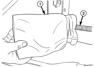
3. Reach through the access hole in the quarter inner panel behind the right rear wheelhouse to locate and retrieve the trailer tow relay connector bank at the end of a take out of the rear body wire harness (2), which is wrapped within a foam rubber envelope (1) and placed on the top of the right rear wheelhouse between the quarter inner and outer panels.
4. Pull the trailer tow relay connector bank envelope into the cargo area far enough to access the relays for service.
5. Carefully remove the trailer tow relay connector bank (1) from the foam wrap.
6. Remove the appropriate relay (3, 4, 5 or 6) by grasping it firmly and pulling it straight out from the connector bank.
INSTALLATION
WARNING: To avoid personal injury or death, on vehicles equipped with airbags, disable the supplemental restraint system before attempting any steering wheel, steering column, airbag, occupant classification system, seat belt tensioner, impact sensor, or instrument panel component diagnosis or service. Disconnect and isolate the battery negative (ground) cable, then wait two minutes for the system capacitor to discharge before performing further diagnosis or service. This is the only sure way to disable the supplemental restraint system. Failure to take the proper precautions could result in accidental airbag deployment.
CAUTION: Use proper precautions to protect your skin and the rear body wire harness from cuts or scrapes caused by contact with the sharp edges of the quarter inner panel sheet metal while servicing the trailer tow relay connector bank.
CAUTION: Be certain any removed trailer tow relay is replaced with the same relay size and type that was removed.
NOTE: The trailer tow relay bank contains four relays. The service procedures for each relay are the same.
1. Position the trailer tow relay (3, 4, 5 or 6) to the appropriate connector in the connector bank (1).
2. Align the relay terminals with the receptacles in the connector.
3. Push firmly and evenly on the top of the relay until the terminals are fully seated in the connector.
4. Carefully restore the foam wrap (1) around the trailer tow relay connector bank on the rear body wire harness take out (2).
5. Reach through the access hole in the quarter inner panel behind the right rear wheelhouse to place the relay connector bank on the top of the right rear wheelhouse between the quarter inner and outer panels.
6. Reinstall the trim onto the right side quarter inner panel. (Refer to 23 - BODY/INTERIOR/QUARTER TRIM PANEL - INSTALLATION).
7. Reconnect the battery negative cable.