*RIGHT REAR DOOR AJAR CIRCUIT OPEN
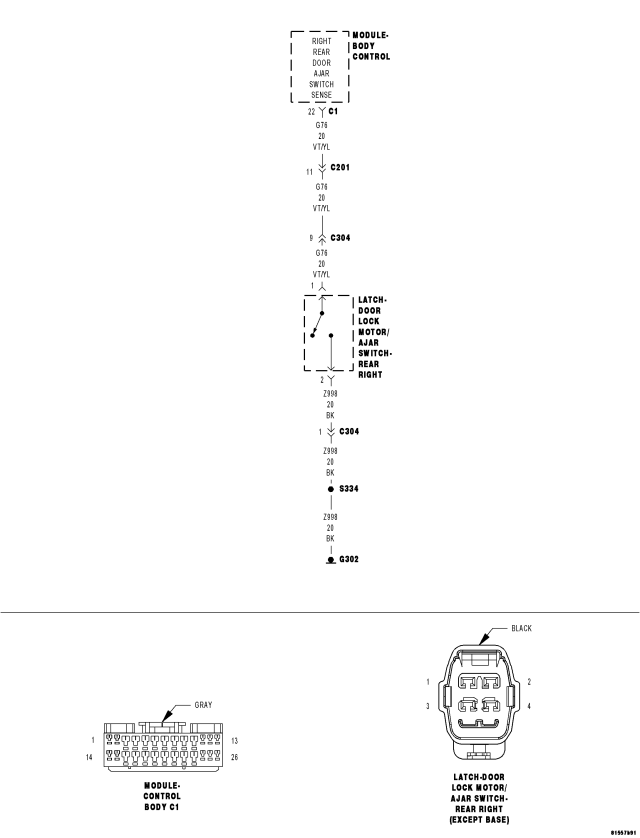
For a complete wiring diagram Refer to Section 8W.
Theory of Operation
The scan tool will display the door state NOT the switch state. It will display as True/False. True states that the door is ajar (open). False states that the door is NOT ajar (closed).
| Possible Causes |
| RIGHT REAR DOOR AJAR SWITCH GROUND CIRCUIT OPEN |
| (G76) RIGHT REAR DOOR AJAR SWITCH SENSE CIRCUIT OPEN |
| DOOR LOCK MOTOR/AJAR SWITCH |
| BODY CONTROL MODULE |
Diagnostic Test
1. OPEN RIGHT REAR DOOR AJAR SWITCH GROUND CIRCUIT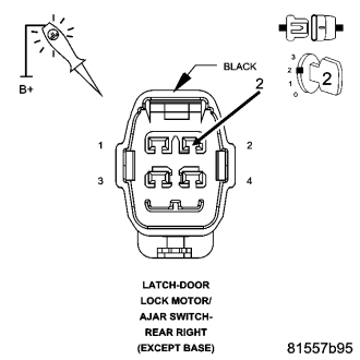
Disconnect the Right Rear Door Lock Motor/Ajar switch connector.
Using a 12-volt Test Light connected to 12-volts, test the Ground circuit.
Does the test light illuminate brightly?
Yes
- Go To2
No
- Repair the Ground circuit for an open.
- Perform BODY VERIFICATION TEST - VER 1. (Refer to 8 - ELECTRICAL/ELECTRONIC CONTROL MODULES - STANDARD PROCEDURE)
2. CHECK FOR OPEN RIGHT FRONT DOOR AJAR SWITCH
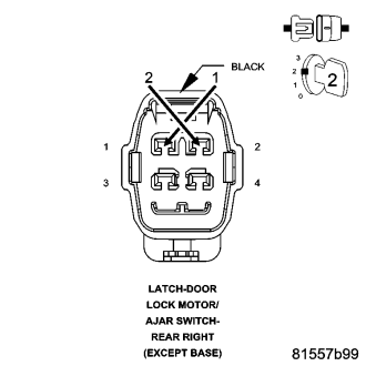
With the scan tool in Data Display, read the RIGHT REAR DOOR AJAR SW state.
Connect a jumper wire between the Sense circuit and the Ground circuit.
Does the scan tool display RIGHT REAR DOOR AJAR SW: TRUE?
Yes
- Replace the Door Lock Motor/Ajar Switch.
- Perform BODY VERIFICATION TEST - VER 1. (Refer to 8 - ELECTRICAL/ELECTRONIC CONTROL MODULES - STANDARD PROCEDURE)
No
- Go To3
3. CHECK FOR OPEN (G76) RIGHT REAR DOOR AJAR SWITCH SENSE CIRCUIT
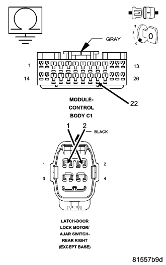
Turn the ignition off.
Leave the jumper wire from the previous step connected.
Disconnect the Body Control Module C1 harness connector.
Measure the resistance between ground and the (G76) Right Rear Door Ajar Switch Sense circuit in the BCM C1 connector.
Is the resistance below 5.0 ohms?
Yes
- Replace the Body Control Module in accordance with service information.
- Perform BODY VERIFICATION TEST - VER 1. (Refer to 8 - ELECTRICAL/ELECTRONIC CONTROL MODULES - STANDARD PROCEDURE)
No
- Repair the (G76) Right Front Door Ajar Switch Sense circuit for an open.
- Perform BODY VERIFICATION TEST - VER 1. (Refer to 8 - ELECTRICAL/ELECTRONIC CONTROL MODULES - STANDARD PROCEDURE)