DIAGNOSIS AND TESTING
MULTI-FUNCTION SWITCH
WARNING: To avoid personal injury or death, on vehicles equipped with airbags, disable the supplemental restraint system before attempting any steering wheel, steering column, airbag, occupant classification system, seat belt tensioner, impact sensor, or instrument panel component diagnosis or service. Disconnect and isolate the battery negative (ground) cable, then wait two minutes for the system capacitor to discharge before performing further diagnosis or service. This is the only sure way to disable the supplemental restraint system. Failure to take the proper precautions could result in accidental airbag deployment.
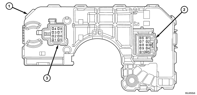
1. Remove the multi-function switch (1) from the steering column. (Refer to 8 - ELECTRICAL/LAMPS/LIGHTING - EXTERIOR/MULTI-FUNCTION SWITCH - REMOVAL).
2. Disconnect the lighting C-1 (2) or wiper C-2 (3) wire harness connector from the back of the multi-function switch.
3. Using an ohmmeter, perform the continuity and resistance tests at the terminals in the multi-function switch connector as shown in the Multi-Function Switch Tests table.
| MULTI-FUNCTION SWITCH TESTS | ||
| EXTERIOR LIGHTING FUNCTIONS | ||
| SWITCH POSITION | CONNECTOR C-1 PINS | RESISTANCE (OHMS) ±10% |
| Off | 4 and 5 | 3781 |
| Park Lamps On | 4 and 5 | 911 |
| Headlamp Low Beams On | 4 and 5 | 349 |
| Rear Fog Lamps On | 4 and 5 | 75 |
| Headlamp High Beams On | 8 and 9 | 0 - 1 |
| Front Fog Lamps On | 2 and 4 | 0 - 1 |
| Optical Horn (Flash-to-Pass) On | 7 and 8 | 0 - 1 |
| Turn Signal Neutral | 6 and 8, 8 and 10 | Infinite (Open) |
| Turn Signal Left | 6 and 8 | 0 - 1 |
| Turn Signal Right | 8 and 10 | 0 - 1 |
| INTERIOR LIGHTING FUNCTIONS | ||
| SWITCH POSITION | CONNECTOR C-1 PINS | RESISTANCE (OHMS) ±10% |
| Off (Courtesy Disable) | 1 and 4 | 63 |
| Dimming 1 | 1 and 4 | 200 |
| Dimming 2 | 1 and 4 | 557 |
| Dimming 3 | 1 and 4 | 914 |
| Dimming 4 | 1 and 4 | 1271 |
| Dimming 5 | 1 and 4 | 1628 |
| Dimming 6 | 1 and 4 | 1985 |
| Parade Mode On | 1 and 4 | 3565 |
| Courtesy On | 1 and 4 | 7885 |
| FRONT WIPER FUNCTIONS | ||
| SWITCH POSITION | CONNECTOR C-1 AND C-2 PINS | RESISTANCE (OHMS) ±10% |
| Front Wiper Off | C-1 Pin 4 and C-2 Pin 4 | 4587 |
| Delay 1 | C-1 Pin 4 and C-2 Pin 4 | 1267 |
| Delay 2 | C-1 Pin 4 and C-2 Pin 4 | 792 |
| Delay 3 | C-1 Pin 4 and C-2 Pin 4 | 531 |
| Delay 4 | C-1 Pin 4 and C-2 Pin 4 | 369 |
| Delay 5 | C-1 Pin 4 and C-2 Pin 4 | 262 |
| Front Wiper Low | C-1 Pin 4 and C-2 Pin 4 | 125 |
| Front Wiper High | C-1 Pin 4 and C-2 Pin 4 | 38 |
| Front Wiper Mist | C-1 Pin 4 and C-2 Pin 4 | 125 |
| Front Washer On | C-2 Pins 5 and 7 | 0 - 1 |
| REAR WIPER FUNCTIONS | ||
| SWITCH POSITION | CONNECTOR C-2 PINS | RESISTANCE (OHMS) ±10% |
| Rear Wiper Off | 1 and 5, 2 and 5 | Infinite (Open) |
| Rear Wiper Intermittent | 2 and 5 | 0 - 1 |
| Rear Wiper On | 1 and 5 | 0 - 1 |
| Rear Washer On | 2 and 5, 3 and 5 | 0 - 1 |
4. If the switch fails any of the tests, replace the ineffective multi-function switch as required.