COUPLER-REFRIGERANT LINE
DESCRIPTION
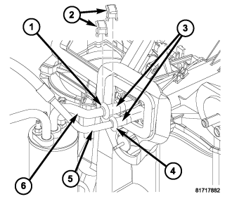
Spring-lock type refrigerant line couplers (1 and 4) are used to connect the A/C liquid and suction lines (5 and 6) to the A/C evaporator tubes (3) on LHD models. Secondary retaining clips (2) are installed over the connected couplers for added protection.
The spring-lock refrigerant line couplers require special disconnect tools for disengaging the two coupler halves.
OPERATION
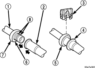
The spring-lock type refrigerant line coupler is held together by a garter spring (6) inside a circular cage (7) on the male half of the fitting (1). When the two coupler halves are connected, the flared end of the female fitting (2) slips behind the garter spring inside the cage on the male fitting. The garter spring and cage prevent the flared end of the female fitting from pulling out of the cage. Some applications use a connection indicator ring (4) to help indicate when the two coupler halves are fully connected.
Two O-rings (8) are used to seal the coupler connections. These O-rings are compatible with R-134a refrigerant and must be replaced with O-rings made of the same material.
A secondary retaining clip (3) is installed over the connected coupler (5) for added protection.
REMOVAL
WARNING: Refer to the applicable warnings and cautions for this system before performing the following operation (refer to 24 - HEATING & AIR CONDITIONING/PLUMBING - WARNING) and (refer to 24 - HEATING & AIR CONDITIONING/PLUMBING - CAUTION). Failure to follow the warnings and cautions could result in possible personal injury or death.
1. Recover the refrigerant from the refrigerant system (refer to 24 - HEATING & AIR CONDITIONING/PLUMBING - STANDARD PROCEDURE - REFRIGERANT SYSTEM RECOVERY).
2. Remove the secondary retaining clip from the spring-lock type refrigerant line coupler.
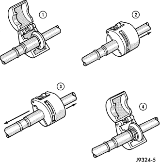
3. Fit the proper size A/C line disconnect tool (Special Tool Kit 7193 or equivalent) over the coupler cage (1).
4. Close the two halves of the A/C line disconnect tool around the coupler (2).
NOTE: The garter spring may not release if the A/C line disconnect tool is cocked while pushing it into the coupler cage opening.
5. Push the A/C line disconnect tool into the open side of the coupler cage to expand the garter spring (3). Once the garter spring is expanded, pull on the refrigerant line attached to the female half of the coupler until the flange on the female fitting is separated from the garter spring and cage on the male fitting.
6. Open and remove the A/C line disconnect tool from the refrigerant line coupler (4).
INSTALLATION
1. Clean any dirt or foreign material from the spring-lock type refrigerant line coupler.
2. Check to make sure that the garter spring (6) is located within the cage (7) of the male half of the refrigerant line coupler (1), and that the garter spring is not damaged.
a. If the garter spring is missing, install a new spring by pushing it into the coupler cage opening.
b. If the garter spring is damaged, remove it from the coupler cage with a small hook (DO NOT use a screwdriver) and install a new garter spring.
CAUTION: Use only the specified O-rings as they are made of a special material for the R-134a system. The use of any other O-rings may allow the connection to leak.
3. Install new O-rings (8) on the male half of the refrigerant line coupler.
4. Lubricate the O-rings, and the inside of the female half of the refrigerant line coupler (2) with clean R-134a refrigerant oil. Use only refrigerant oil of the type recommended for the A/C compressor in the vehicle.
5. Position the female half of the coupler over the male half of the coupler.
6. Push together firmly on the two halves of the refrigerant line coupler until the garter spring in the cage on the male half of the coupler snaps over the flanged end on the female half of the coupler.
7. Make sure that the refrigerant line coupler is fully engaged by firmly pulling the refrigerant lines away from each other on both sides of the coupler.
8. Install the secondary retaining clip (3) over connected coupler cage (5).
9. Evacuate the refrigerant system (refer to 24 - HEATING & AIR CONDITIONING/PLUMBING - STANDARD PROCEDURE - REFRIGERANT SYSTEM EVACUATE).
10. Charge the refrigerant system (refer to 24 - HEATING & AIR CONDITIONING/PLUMBING - STANDARD PROCEDURE - REFRIGERANT SYSTEM CHARGE).