MICRO-RELAY
DESCRIPTION
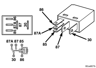
A micro-relay is a conventional International Standards Organization (ISO) micro relay. Relays conforming to the ISO specifications have common physical dimensions, current capacities, terminal patterns, and terminal functions. The relay is contained within a small, rectangular, molded plastic housing and is connected to all of the required inputs and outputs by five integral male spade-type terminals that extend from the bottom of the relay base.
Relays cannot be adjusted or repaired and, if faulty or damaged, the unit must be replaced.
OPERATION
A micro-relay is an electromechanical switch that uses a low current input from one source to control a high current output to another device. The movable common feed contact point is held against the fixed normally closed contact point by spring pressure. When the relay coil is energized, an electromagnetic field is produced by the coil windings. This electromagnetic field draws the movable relay contact point away from the fixed normally closed contact point, and holds it against the fixed normally open contact point. When the relay coil is de-energized, spring pressure returns the movable contact point back against the fixed normally closed contact point. A resistor is connected in parallel with the relay coil in the relay, and helps to dissipate voltage spikes and electromagnetic interference that can be generated as the electromagnetic field of the relay coil collapses.
DIAGNOSIS AND TESTING - MICRO-RELAY
1. Remove the relay from its mounting location.
2. A relay in the de-energized position should have continuity between terminals 87A and 30, and no continuity between terminals 87 and 30. If OK, go to STEP 3. If not OK, replace the faulty relay.
3. Resistance between terminals 85 and 86 (electromagnet) should be 67.5 - 82.5 ohms. If OK, go to STEP 4. If not OK, replace the faulty relay.
4. Connect a battery to terminals 85 and 86. There should now be continuity between terminals 30 and 87, and no continuity between terminals 87A and 30. If OK, reinstall the relay and use a DRBIII® scan tool to perform further testing. Refer to the appropriate diagnostic information.
Refer to the appropriate wiring information. The wiring information includes wiring diagrams, proper wire and connector repair procedures, details of wire harness routing and retention, connector pin-out information and location views for the various wire harness connectors, splices and grounds.
REMOVAL
1. Disconnect and isolate the negative battery cable.
2. Remove the relay by grasping it firmly and pulling it straight out from its receptacle. A slight back and fourth rocking motion may help the removal process.
INSTALLATION
1. Align the micro-relay terminals with the terminal cavities in the receptacle.
2. Push firmly and evenly on the top of the relay until the terminals are fully seated in the terminal cavities in the receptacle.
3. Connect the battery negative cable.