RELAY
DESCRIPTION
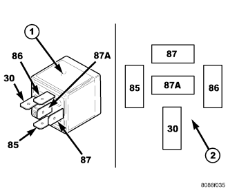
A relay is an electromechanical device that switches fused battery current to a electrical component when the ignition switch is turned to the Accessory or Run positions, or when controlled by a electronic module. The relays are located in the junction block or power distribution center.
The relay is a International Standards Organization (ISO) relay. Relays conforming to the ISO specifications have common physical dimensions, current capacities, terminal patterns, and terminal functions.
A relay cannot be repaired or adjusted and, if faulty or damaged, it must be replaced.
OPERATION
The ISO relay consists of an electromagnetic coil, a resistor and three (two fixed and one movable) electrical contacts. The movable (common feed) relay contact is held against one of the fixed contacts (normally closed) by spring pressure. When the electromagnetic coil is energized, it draws the movable contact away from the normally closed fixed contact, and holds it against the other (normally open) fixed contact.
When the electromagnetic coil is de-energized, spring pressure returns the movable contact to the normally closed position. The resistor is connected in parallel with the electromagnetic coil in the relay, and helps to dissipate voltage spikes that are produced when the coil is de-energized.
DIAGNOSIS AND TESTING - RELAY
The relays are located in the junction block or power distribution center. For complete circuit diagrams, refer to Wiring Diagrams .
1. Remove the relay from its mounting location.
2. A relay in the de-energized position should have continuity between terminals 87A and 30, and no continuity between terminals 87 and 30. If OK, go to STEP 3. If not OK, replace the faulty relay.
3. Resistance between terminals 85 and 86 (electromagnet) should be 60.7 - 80.3 ohms. If OK, go to STEP 4. If not OK, replace the faulty relay.
4. Connect a battery to terminals 85 and 86. There should now be continuity between terminals 30 and 87, and no continuity between terminals 87A and 30. If OK, perform the Relay Circuit Test that follows. If not OK, replace the faulty relay.
DIAGNOSIS & TESTING - RELAY CIRCUIT TEST
1. The relay common feed terminal cavity (30) of the junction block or power distribution center is connected to battery voltage and should be hot at all times. Check for battery voltage at the fused B(+) circuit cavity in the junction block receptacle for the relay. If OK, go to STEP 2. If not OK, repair the fused B(+) circuit to the Power Distribution Center (PDC) fuse as required.
2. The relay normally closed terminal (87A) is connected to terminal 30 in the de-energized position, but is not used for this application. Go to STEP 3.
3. The relay normally open terminal (87) is connected to the common feed terminal (30) in the energized position. This terminal supplies battery voltage to the fused B(+) fuse in the junction block that feeds the accessory when the relay is energized by the ignition switch. There should be continuity between the junction block cavity for relay terminal 87 and the fused B(+) fuse in the junction block at all times. If OK, go to STEP 4. If not OK, repair the open fused B(+) circuit to the junction block fuse as required.
4. The coil ground terminal (85) is connected to the electromagnet in the relay. It receives battery feed to energize the relay when the ignition switch is in the Accessory or Run positions. Turn the ignition switch to the On position. Check for battery voltage at the fused ignition switch output (acc/run) circuit cavity for relay terminal 85 in the junction block receptacle for the relay. If OK, go to STEP 5. If not OK, repair the open fused ignition switch output (acc/run) circuit to the ignition switch as required.
5. The coil battery terminal (86) is connected to the electromagnet in the relay. The junction block cavity for this terminal should have continuity to ground at all times. If not OK, repair the open ground circuit to ground as required.
REMOVAL
1. Disconnect and isolate the negative battery cable.
2. Remove the relay by grasping it firmly and pulling it straight out from its receptacle. A slight back and fourth rocking motion may help the removal process.
INSTALLATION
1. Position the relay to the proper receptacle.
2. Align the relay terminals with the terminal cavities in the receptacle.
3. Push firmly and evenly on the top of the relay until the terminals are fully seated in the terminal cavities in the receptacle.
4. Connect the negative battery cable.