DOOR LOCK SWITCH OPEN OR SHORT TO VOLTAGE
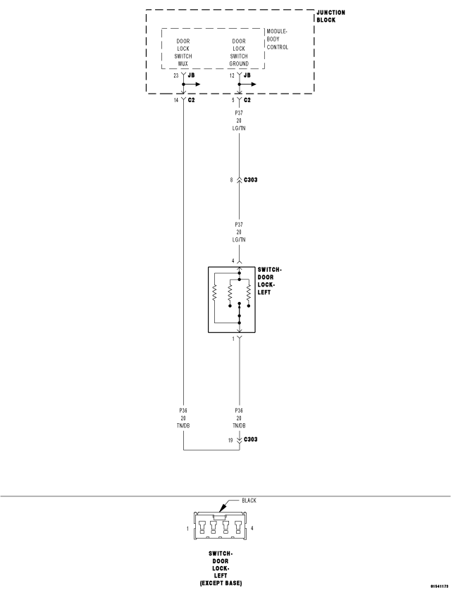
For a complete wiring diagram Refer to Section 8W.
- When Monitored:
Whenever the ignition is on.
- Set Condition:
When the BCM detects a voltage of greater than 4.75 volts on the door lock switch mux input for over 5 seconds, this code will set. The normal voltage on the circuit is between 0.25 and 4.75 volts depending on switch positions. NOTE: Left and right switches are in parallel.
| Possible Causes |
| (P37) LEFT DOOR LOCK SWITCH GND WIRE OPEN |
| (P36) LEFT DOOR LOCK SWITCH MUX WIRE OPEN |
| (P36) LEFT DOOR LOCK SWITCH MUX WIRE SHORT TO VOLTAGE |
| (P37) RIGHT DOOR LOCK SWITCH GND WIRE OPEN |
| (P36) RIGHT DOOR LOCK SWITCH MUX WIRE OPEN |
| (P36) RIGHT DOOR LOCK SWITCH MUX WIRE SHORT TO VOLTAGE |
| LEFT DOOR LOCK SWITCH - OPEN |
| LEFT DOOR LOCK SWITCH - SHORTED |
| RIGHT DOOR LOCK SWITCH - OPEN |
| RIGHT DOOR LOCK SWITCH - SHORTED |
| JUNCTION BLOCK OPEN |
| BODY CONTROL MODULE - DOOR LOCK SWITCH MUX OPEN |
Diagnostic Test
1. CHECK TROUBLE CODETurn the ignition on.
With the scan tool, erase DTCs.
Operate the door locks several times from both door lock switches
With the scan tool read DTCs.
Does the scan tool display DOOR LOCK SWITCH OPEN OR SHORT TO VOLTAGE?
Yes
- Go To2
No
- Problem is intermittent and not present at this time. Using the wiring diagram/schematic as a guide, inspect the wiring and connectors and repair as necessary.
- Perform BODY VERIFICATION TEST - VER 1. (Refer to 8 - ELECTRICAL/ELECTRONIC CONTROL MODULES - STANDARD PROCEDURE)
2. CHECK DOOR LOCK SWITCH MUX CIRCUIT FOR A SHORT TO VOLTAGE
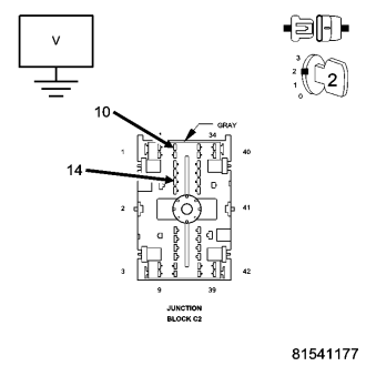
Disconnect the Junction Block C2 connector.
Measure the voltage between ground and the (P36) Door Lock Switch Mux circuit cavity 14 in the C2 connector.
Measure the voltage between ground and the (P36) Door Lock Switch Mux circuit cavity 10 in the C2 connector.
Which cavity had greater than 0.5 volts?
Cavity 14 - Left Door
- Go To3
Cavity 10 - Right Door
- Go To4
Neither circuit over 0.5 volts.
- Go To5
3. CHECK LEFT DOOR LOCK SWITCH MUX WIRE FOR A SHORT TO VOLTAGE
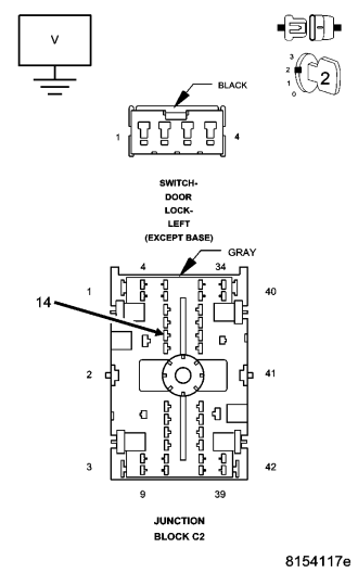
Disconnect the Left Door Lock Switch connector.
Measure the voltage between ground and the (P36) Door Lock Switch Mux circuit cavity 14 in the JB-C2 connector.
Is there any voltage present?
Yes
- Repair the (P36) Door Lock Switch Mux wire for a short to voltage.
- Perform BODY VERIFICATION TEST - VER 1. (Refer to 8 - ELECTRICAL/ELECTRONIC CONTROL MODULES - STANDARD PROCEDURE)
No
- Replace the Left Door Lock Switch.
- Perform BODY VERIFICATION TEST - VER 1. (Refer to 8 - ELECTRICAL/ELECTRONIC CONTROL MODULES - STANDARD PROCEDURE)
4. CHECK RIGHT DOOR LOCK SWITCH MUX WIRE FOR A SHORT TO VOLTAGE
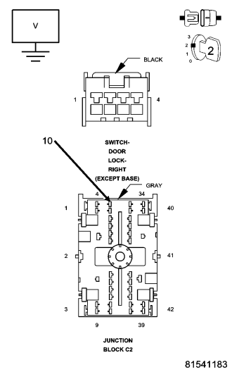
Disconnect the Right Door Lock Switch connector.
Measure the voltage between ground and the (P36) Door Lock Switch Mux circuit cavity 10 in the JB-C2 connector.
Is there any voltage present?
Yes
- Repair the (P36) Door Lock Switch Mux wire for a short to voltage.
- Perform BODY VERIFICATION TEST - VER 1. (Refer to 8 - ELECTRICAL/ELECTRONIC CONTROL MODULES - STANDARD PROCEDURE)
No
- Replace the Right Door Lock Switch.
- Perform BODY VERIFICATION TEST - VER 1. (Refer to 8 - ELECTRICAL/ELECTRONIC CONTROL MODULES - STANDARD PROCEDURE)
5. CHECK DOOR LOCK SWITCH MUX CIRCUIT FOR AN OPEN
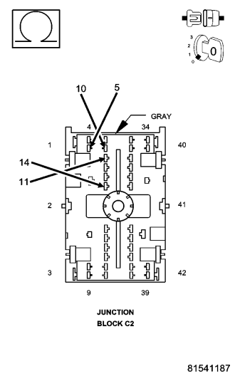
Turn the ignition off.
Measure the resistance between the (P37) Door Lock Switch Ground cavity 5 and the (P36) Door Lock Switch Mux circuit cavity 10 in the JB-C2 connector.
Measure the resistance between the (P37) Door Lock Switch Ground cavity 11 and the (P36) Door Lock Switch Mux circuit cavity 14 in the JB-C2 connector.
Which circuit was NOT between 4500 and 5500 ohms?
Cavities 5 & 10 - Right Door
- Go To6
Cavities 11 & 14 - Left Door
- Go To8
Both were approximately 5000 ohms.
- Go To10
6. CHECK RIGHT DOOR LOCK SWITCH MUX WIRE FOR AN OPEN
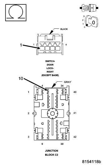
Disconnect the Right Door Lock Switch connector.
Measure the resistance of the (P36) Door Lock Switch Mux circuit between cavity 10 in the JB-C2 connector and the Right Door Lock Switch connector.
Is the resistance below 5.0 ohms?
Yes
- Go To7
No
- Repair the (P36) Door Lock Switch Mux wire for an open.
- Perform BODY VERIFICATION TEST - VER 1. (Refer to 8 - ELECTRICAL/ELECTRONIC CONTROL MODULES - STANDARD PROCEDURE)
7. CHECK RIGHT DOOR LOCK SWITCH GROUND WIRE FOR AN OPEN
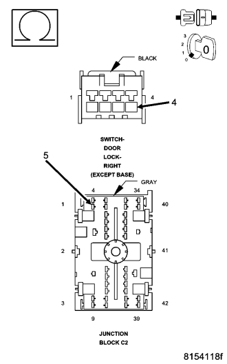
Measure the resistance of the (P37) Door Lock Switch Ground circuit between cavity 5 in the JB-C2 connector and the Right Door Lock Switch connector.
Is the resistance below 5.0 ohms?
Yes
- Replace the Right Door Lock Switch.
- Perform BODY VERIFICATION TEST - VER 1. (Refer to 8 - ELECTRICAL/ELECTRONIC CONTROL MODULES - STANDARD PROCEDURE)
No
- Repair the (P37) Door Lock Switch Ground wire for an open.
- Perform BODY VERIFICATION TEST - VER 1. (Refer to 8 - ELECTRICAL/ELECTRONIC CONTROL MODULES - STANDARD PROCEDURE)
8. CHECK LEFT DOOR LOCK SWITCH MUX WIRE FOR AN OPEN
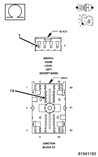
Disconnect the Left Door Lock Switch connector.
Measure the resistance of the (P36) Door Lock Switch Mux circuit between cavity 14 in the JB-C2 connector and the Left Door Lock Switch connector.
Is the resistance below 5.0 ohms?
Yes
- Go To9
No
- Repair the (P36) Door Lock Switch Mux wire for an open.
- Perform BODY VERIFICATION TEST - VER 1. (Refer to 8 - ELECTRICAL/ELECTRONIC CONTROL MODULES - STANDARD PROCEDURE)
9. CHECK LEFT DOOR LOCK SWITCH GROUND WIRE FOR AN OPEN
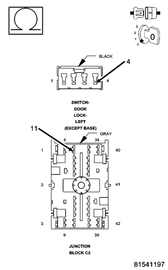
Measure the resistance of the (P37) Door Lock Switch Ground circuit between cavity 11 in the JB-C2 connector and the Left Door Lock Switch connector.
Is the resistance below 5.0 ohms?
Yes
- Replace the Left Door Lock Switch.
- Perform BODY VERIFICATION TEST - VER 1. (Refer to 8 - ELECTRICAL/ELECTRONIC CONTROL MODULES - STANDARD PROCEDURE)
No
- Repair the (P37) Door Lock Switch Ground wire for an open.
- Perform BODY VERIFICATION TEST - VER 1. (Refer to 8 - ELECTRICAL/ELECTRONIC CONTROL MODULES - STANDARD PROCEDURE)
10. CHECK THE JUNCTION BLOCK FOR AN OPEN
Disconnect the battery ground cable.
Disconnect all the Junction Block connectors and remove the Junction Block.
Remove the Body Control Module from the Junction Block.
NOTE: Make all measurements in the Junction Block – NOT the harness connector.
Measure the resistance of the (P36) Door Lock Switch Mux circuit between cavity 23 in the Junction Block - Body Control Module connector and cavity 10 in the Junction Block C2.
Measure the resistance of the (P36) Door Lock Switch Mux circuit between cavity 23 in the Junction Block - Body Control Module connector and cavity 14 in the Junction Block C2.
Measure the resistance of the (P37) Door Lock Switch Ground circuit between cavity 12 in the Junction Block - Body Control Module connector and cavity 5 in the Junction Block C2.
Measure the resistance of the (P37) Door Lock Switch Ground circuit between cavity 12 in the Junction Block - Body Control Module connector and cavity 11 in the Junction Block C2.
Is the resistance below 1.0 ohm for each circuit?
Yes
- Replace the Body Control Module.
- Perform BODY VERIFICATION TEST - VER 1. (Refer to 8 - ELECTRICAL/ELECTRONIC CONTROL MODULES - STANDARD PROCEDURE)
No
- Replace the Junction Block.
- Perform BODY VERIFICATION TEST - VER 1. (Refer to 8 - ELECTRICAL/ELECTRONIC CONTROL MODULES - STANDARD PROCEDURE)