TAILGATE CYLINDER LOCK SWITCH
DESCRIPTION
The tailgate cylinder lock switch is integral to the key lock cylinder inside the tailgate. The tailgate cylinder lock switch is a normally-open momentary switch that is hard wired directly to the Body Control Module (BCM), and closes a path to ground through an internal resistor when the lock cylinder is rotated to the unlock or lock position.
The tailgate cylinder lock switch cannot be adjusted or repaired.
OPERATION
The tailgate cylinder lock switch is actuated when the key is inserted in the lock cylinder and turned to the unlock or lock position. The tailgate cylinder lock switch closes a path to ground through an internal resistor for the Body Control Module (BCM) when the tailgate key lock cylinder is in the lock or unlock position, and opens the ground path when the lock cylinder is in the neutral position. The BCM reads the switch status, then sends the proper switch status messages to other electronic modules over the Programmable Communications Interface (PCI) data bus network. The tailgate cylinder lock switch unlock status message is used by the BCM as an input for Vehicle Theft Security System (VTSS) operation and to tell the BCM to lock or unlock the tailgate. There is no mechanical linkage between the tailgate key cylinder and the latches.
REMOVAL
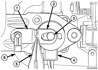
1. Disconnect and isolate the battery negative cable.
2. Remove the tailgate trim panel. (Refer to 23 - BODY/DECKLID/HATCH/LIFTGATE/TAILGATE/TRIM PANEL - REMOVAL).
3. Remove the retainer clip from the pin on the back of the door lock cylinder (3).
4. Remove the washer from the pin on the back of the door lock cylinder.
5. Remove the door cylinder lock switch (4) from the back of the lock cylinder.
INSTALLATION
1. Position the tailgate cylinder lock switch (4) onto the back of the lock cylinder (3) with the wire harness oriented toward the bottom.
2. Position the washer over the switch.
3. Install the retainer (2) clip onto the pin on the back of the tailgate lock cylinder. Be certain that the center tab of the retainer is engaged in the retention hole on the lock lever.
4. Install the trim panel (Refer to 23 - BODY/DECKLID/HATCH/LIFTGATE/TAILGATE/TRIM PANEL - INSTALLATION).
5. Connect the battery negative cable.