POWER SEAT TRACK
DESCRIPTION
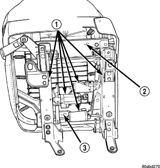
The six-way power seat option includes a power seat track assembly (3) located under each front seat cushion frame (2). The power seat track assembly replaces the standard manually operated seat tracks. The lower half of the power seat track is secured at the front with two bolts to the floor panel seat cross member, and at the rear with one bolt and one nut to the floor panel. Four bolts secure the bottom of the seat cushion frame to the upper half of the power seat track unit.
The power seat track assembly cannot be repaired, and is serviced only as a complete assembly. If any component in this assembly is faulty or damaged, the entire power seat track must be replaced.
OPERATION
The power seat track unit includes three reversible electric motors that are secured to the upper half of the track unit. Each motor moves the seat adjuster through a combination of worm-drive gearboxes and screw-type drive units. Each of the three driver side power seat track motors also has a position potentiometer integral to the motor assembly, which electronically monitors the motor position.
The front and rear of the seat are operated by two separate vertical adjustment motors. These motors can be operated independently of each other, tilting the entire seat assembly forward or rearward; or, they can be operated in unison by selecting the proper power seat switch functions, which will raise or lower the entire seat assembly. The third motor is the horizontal adjustment motor, which moves the seat track in the forward and rearward directions.
DIAGNOSIS AND TESTING - POWER SEAT TRACK
1. Remove the power seat switch from the seat (Refer to 8 - ELECTRICAL/POWER SEATS/DRIVER SEAT SWITCH - REMOVAL).
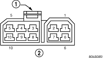
2. Checking the body harness side of the power seat switch electrical connector, check Pin 1 for ground and Pin 5 for battery voltage. If either of these two are not present repair the body harness as required.
3. To test the seat motors and verify proper seat responses, refer to the SEAT TRACK MOTOR TEST TABLE. Using two jumper wires, connect one to a battery supply and the second to a ground. Connect the other ends to the seat wire harness connector as described in the SEAT TRACK MOTOR TEST TABLE.
| SEAT SWITCH CONNECTOR | |||
| CONNECT JUMPER | SEAT ACTION | ||
| B(+) | B(–) | LEFT SIDE | RIGHT SIDE |
| PIN 9 | PIN 8 | FRONT RISER UP | FRONT RISER DOWN |
| PIN 8 | PIN 9 | FRONT RISER DOWN | FRONT RISER UP |
| PIN 3 | PIN 6 | FORWARD | FORWARD |
| PIN 6 | PIN 3 | REARWARD | REARWARD |
| PIN 10 | PIN 7 | REAR RISER UP | REAR RISER DOWN |
| PIN 7 | PIN 10 | REAR RISER DOWN | REAR RISER UP |
REMOVAL
1. Remove the appropriate seat from the vehicle. (Refer to 23 - BODY/SEATS/SEAT - REMOVAL).
2. Remove the seat cushion side shield from the seat (Refer to 23 - BODY/SEATS/SEAT CUSHION SIDE COVERS - REMOVAL).
3. Remove four seat track mounting bolts from cushion pan.
4. Disconnect the power seat electrical and remove the seat track from the seat cushion.
INSTALLATION
1. Position the seat track and install the retaining bolts in the seat cushion pan. Torque the bolts to 45-60 N·m.
2. Route and connect the power seat electrical on the seat track and cushion pan.
3. Install the seat cushion side shield on the seat. Refer to the Body section for the procedure.
4. Install the seat in the vehicle (Refer to 23 - BODY/SEATS/SEAT - INSTALLATION).
5. Connect the negative battery cable.