GEAR-PINION/RING
REMOVAL
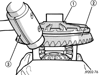
NOTE: The ring and pinion gears are serviced in a matched set. Never replace one gear without replacing the other matched gear.
1. Remove differential from axle housing.
2. Place differential case (1) in a vise with soft metal jaw .
3. Remove bolts holding ring gear (2) to differential case.
4. Drive ring gear from differential case with a dead-blow hammer (3).
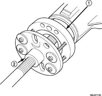
5. Hold flange (1) with Holder 6719A and remove flange nut and washer.
6. Remove flange (1) from pinion shaft with Puller C-452 (2).
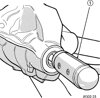
7. Remove pinion from the housing with dead-blow hammer (1).
8. Remove pinion shaft seal with a seal pick.
9. Remove oil slinger, if equipped, and front pinion bearing.
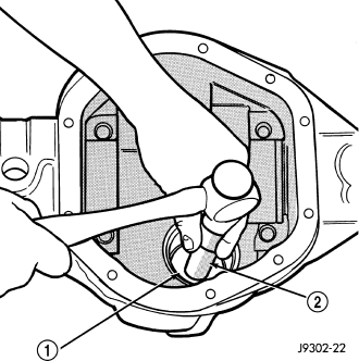
10. Remove front pinion bearing cup with Remover C-4345 (1) and Handle C-4171 (2).
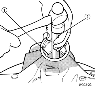
11. Remove rear bearing cup with Remover C-4307 (1) and Handle C-4171 (2).
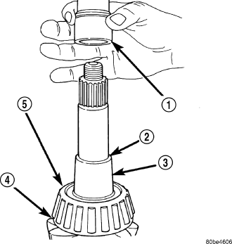
12. Remove collapsible spacer (1) from pinion (3).
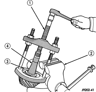
13. Remove rear pinion bearing with Puller/Press C-293-PA (1) and Adapters C-293-47 (3).
14. Remove depth shims from the pinion shaft and record the shims thickness.
INSTALLATION
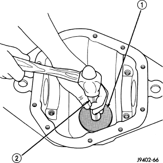
NOTE: A pinion depth shim/oil baffle is located under the rear pinion bearing. If ring and pinion gears are reused, the original pinion depth shim/oil baffle can be used. Refer to Adjustments (Pinion Gear Depth) to select the proper shim thickness if ring and pinion gear are replaced.
1. Install rear pinion bearing cup with Installer C-4308 (1) and Handle C-4171 (2).
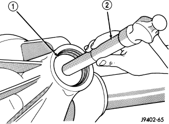
2. Install front pinion bearing cup with Installer D-130 (1) and Handle C-4171 (2).
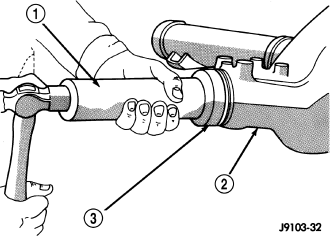
3. Install pinion front bearing and oil slinger, if equipped.
4. Apply a light coating of gear lubricant on the lip of pinion seal and install seal with Installer C-4076-B (3) and Handle C-4735 (1).
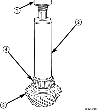
5. Place pinion depth shim on the pinion.
6. Install rear bearing (4) on pinion gear (3) and slinger if equipped, with Installer 6448A (2) and a press (1).
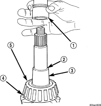
7. Install a new collapsible spacer (1) on pinion shaft (3) and install pinion in housing.
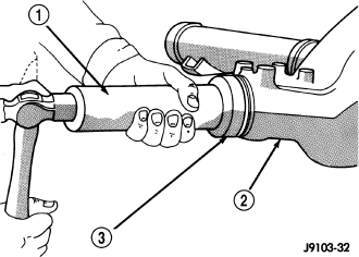
8. Install new pinion seal with Installer C-4076-B (3) and Handle C-4735 (1).
9. Install companion flange with Installer C-3718 and Holder 6719A.
10. Install flange washer and a new nut on the pinion. The convex side of the washer must face outward.
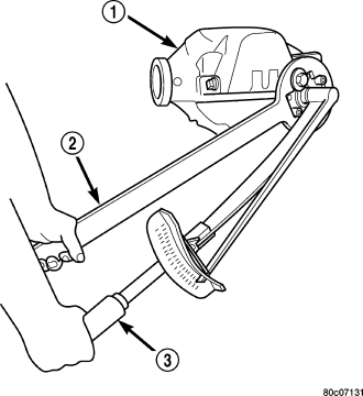
11. Holding flange with Holder 6719A (2) and tighten nut with torque wrench (3) to 285 N·m (210 ft. lbs.).
CAUTION: Never loosen pinion nut to decrease pinion rotating torque and never exceed specified preload torque. Failure to heed caution may result in damage.
12. Hold flange with Holder 6719A and slowly tighten the nut in 6.8 N·m (5 ft. lbs.) increments until pinion torque to rotating is achieved. Measure rotating torque frequently to avoid over crushing the spacer.
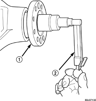
13. Check pinion torque to rotating (1) with an inch pound torque wrench (2). Pinion Torque To Rotating is:
- Original Bearings: 1 to 2 N·m (10 to 20 in. lbs.).
- New Bearings: 1 to 3.4 N·m (10 to 30 in. lbs.).
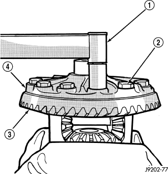
14. Install ring gear (3) on differential case (4) and start two ring gear bolts (2).
15. Invert differential case in the vise.
16. Install new ring gear bolts and alternately tighten to 102 N·m (75 ft. lbs.) .
CAUTION: Never reuse the ring gear bolts. Failure to follow these instructions will result in damage.
17. Install differential in axle housing and verify gear mesh refer to Adjustments (Gear Contact Pattern).